18
Removal of major components
IMPORTANT Before opening the case, disconnect the NIPPY+ from the
mains supply.
Do not work on the NIPPY+ with the case open and the power supply
connected.
Make sure that all precautions to prevent Electrostatic Discharge (ESD)
have been taken.
Do not use explosive gases and/or fluids near the NIPPY+.
Unscrew the 7 case screws to separate the two halves of the case.
Disconnect the board to board ribbon cable and the RS232 lead (fig 1). Lay
the ventilator lid next to the base.
The Battery
Refer to fig 2
Disconnect the battery connector (4). There is no need to remove the board to
do this. Support the corner of the board with thumb and forefinger and gently
wiggle the connector downwards until it comes free.
Remove the battery clamp by removing the 2 M4 x 10 screws.
Remove the battery.
Reverse this procedure to refit.
The Power Supply
Refer to fig 2.
Disconnect the 2 way mains connector and the earth terminal.
Disconnect the 12 way output connector.
Remove the 4 securing screws and lift the power supply out of the case.
Reverse this procedure to refit.
The Control Board
Refer to fig 2.
Disconnect the internal battery first.
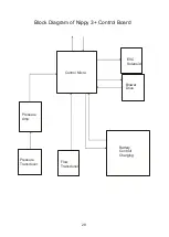
Disconnect the 3 Molex connectors. (Int Battery, PSU, Ext Battery, Cooling
fan).
Disconnect the blower connector.
Disconnect the 4mm silicon tubes from the pressure and flow transducers.
Disconnect the green and yellow small bore tubes from the Exhale valve
control solenoid. Located on the underside of the board.
Remove the 4 securing screws.
To refit:-
Connect the 2 small bore tubes. NOTE: the green tubes fits on the port
nearest the back edge of the board. The yellow tube fits on the adjacent port.
If the ends of the tubes are stretched, trim off approx. 2mm of tube.
Connect the PSU and connector.
Place the board into the lid and fit the 4 mounting screws.
Summary of Contents for Nippy 3+
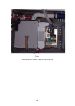
Page 18: ...16 Fig 3 Inside the base with the control board removed...
Page 32: ...30...
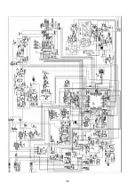
Page 33: ...31 Circuit Diagrams...
Page 34: ...32...
Page 35: ...33 0901 0901 PCB assembly for Control Board primary side 16 11 07...
Page 36: ...34 0901 0901 PCB assembly for Control Board secondary side 16 11 07...
Page 37: ...35 0756 C 17 02 04 A4 1 1 Component Layout for Nippy 3 Command Board 0756 C...
Page 38: ...36...
Page 39: ...37...
Page 40: ...38...
Page 41: ...39...
Page 42: ...40...
Page 43: ...41...
Page 44: ...42 4 7 0 0 u F...


