22
Suggested Acceptance Test
Visual Inspection
Check the NIPPY+ for transit damage.
Functional Tests
Connect a breathing circuit and test lung to the patient outlet and check
function of modes.
Maximum Pressure
Set IPAP to maximum and ensure NIPPY+ achieves set pressure.
Alarm tests
Disconnect the breathing circuit and allow the flow to exceed the high flow
alarm. A visual and audible high flow alarm will be activated after 5 seconds.
The disconnection alarm will follow after 10 seconds.
Occlude the patient outlet. A visual and audible alarm will be activated after
10 seconds.
(NIPPY S+ and ST+ display a disconnection alarm only)
Internal Battery
When fitted the internal battery icon is displayed on the screen.
Switch off the mains supply to the NIPPY+ when it is running and ensure that
the “Running on Battery Power” message is displayed and continues until the
mute button is pressed.
Buttons
Check each button on the keypad functions correctly.
Help
Ensure help window is available for each button.
Electrical Safety Test
NIPPY+ devices are Class I, type B.
Summary of Contents for Nippy 3+
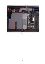
Page 18: ...16 Fig 3 Inside the base with the control board removed...
Page 32: ...30...
Page 33: ...31 Circuit Diagrams...
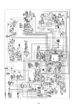
Page 34: ...32...
Page 35: ...33 0901 0901 PCB assembly for Control Board primary side 16 11 07...
Page 36: ...34 0901 0901 PCB assembly for Control Board secondary side 16 11 07...
Page 37: ...35 0756 C 17 02 04 A4 1 1 Component Layout for Nippy 3 Command Board 0756 C...
Page 38: ...36...
Page 39: ...37...
Page 40: ...38...
Page 41: ...39...
Page 42: ...40...
Page 43: ...41...
Page 44: ...42 4 7 0 0 u F...


