24
Replacement of the pcb mounted Alarm Battery
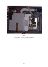
Open the case. See fig 1.
Locate the battery switch on the command board (Item 3, fig 4) marked SW3
on the pcb.
When viewed from the front, the right hand DIP switch (marked BATT on the
pcb) is the battery isolation switch. It is normally in the ON position.
The left hand one of the pair (marked MEM CLR on the pcb) is the memory
reset switch. It is normally in the OFF position
Before attempting to remove the battery
, set BATT to the OFF position
then MEM CLR to the ON position.
Using a fine pair of wire cutters, snip the legs of the battery (item 10, fig 4)
and remove the battery. Carefully remove the remaining legs and solder from
the pcb.
Take a new battery and tin the legs. This is important, as it will clean off any
tarnish that would make soldering difficult. Bad soldering could cause
irreparable damage to the pcb.
Cut the legs to a suitable length for pcb mounting (approx. 2mm). Solder the
battery in place from the component side. Inspect the joints for proper wetting.
Reset the Dip switches. MEM CLR to the OFF position and then BATT to the
ON position.
Double check the switch settings.
Note:
If the switch markings have become illegible, ON is towards the rear of
the case and OFF is towards the front
After changing the battery, the date and time will need to be reset.
Summary of Contents for Nippy 3+
Page 18: ...16 Fig 3 Inside the base with the control board removed...
Page 32: ...30...
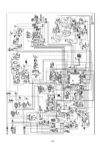
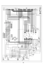
Page 33: ...31 Circuit Diagrams...
Page 34: ...32...
Page 35: ...33 0901 0901 PCB assembly for Control Board primary side 16 11 07...
Page 36: ...34 0901 0901 PCB assembly for Control Board secondary side 16 11 07...
Page 37: ...35 0756 C 17 02 04 A4 1 1 Component Layout for Nippy 3 Command Board 0756 C...
Page 38: ...36...
Page 39: ...37...
Page 40: ...38...
Page 41: ...39...
Page 42: ...40...
Page 43: ...41...
Page 44: ...42 4 7 0 0 u F...

