background image


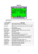
Alarms


Power Fail


If  the  electrical  power  to  the  ventilator  is  interrupted,  an  audible 

alarm will sound. This alarm will run for 5 minutes unless cancelled with the mute 
button. Once cancelled the power fail alarm will not re-activate.  

Low Internal Battery


When running on its internal battery, the alarm will operate when 

the battery is low. This could last for up to 1 hour. When the alarm becomes constant 
there is approximately 10 minutes running time left. 

Low External Battery 

When  running  on  its  external  battery,  the  alarm  will  operate 

when  the  battery  is  low.  This  could  last for  up to  1  hour. When the  alarm  becomes 
constant there is approximately 10 minutes running time left. 

Low Pressure 

A pre-set low pressure alarm is provided. If the control pressure falls 

to  below  50%  of the  set  IPAP  level for  10  seconds  an  audible  and  visual  alarm  will 
operate.  

High Pressure


A pre-set high-pressure alarm is provided. If the pressure rises above 

120% of the working pressure, an audible and visual alarm will operate after a 2 second 
delay. 

Breathing Circuit Disconnect

  A disconnection alarm is provided as a back up to 

the high flow alarm. If the patients flow waveform indicates that a significant leak 
maybe present in the breathing circuit an audible and visual alarm will operate. 
The sensitivity of the alarm is adjustable

Breathing Circuit Malfunction

  This  alarm  warns  of  a  malfunction  of  the  exhale 

valve in the IPPV mode circuit.


High Flow alarm

  An adjustable alarm is provided to warn of excess inspiratory flow. 

This is activated when the inspiratory flow exceeds the set high flow alarm level 
for 5 seconds. An audible and visual alarm will operate. 

Low Flow alarm

 An adjustable alarm is provided to warn of insufficient inspiratory 

flow. This is activated when the inspiratory flow fails to achieve the set low flow 
alarm level for 10 seconds. An audible and visual alarm will operate. 

Apnoea  Alarm 

An  adjustable  Apnoea  alarm  is  provided.  If  an  apnoea  is  detected  an 

audible alarm will sound with a visual indication on screen.


Max Breath Rate 

An  adjustable  maximum  breath  rate  alarm  is  provided.  If  the  max 

breath rate is exceeded an audible and visual alarm will operate.


Fault

 The alarm may also be operated by an internal fault. In this case the fault will be 

displayed on screen. 

These alarms may be muted for approximately 2 minutes to allow for setting up of 
the ventilator. 

Low  Internal  Alarm/Memory  Battery

  An  intermittent  alarm  (short  beep)  with  no 

onscreen message indicates a depleted mains fail alarm battery. If the ventilator has 
been stored for more than a few weeks the internal battery will self-discharge. In this 
case the alarm will stop after the battery has recharged. 

Summary of Contents for Nippy 3+

Page 1: ...rmation and it is supplied on the understanding that it shall not be copied loaned or distributed to any other persons or organisations in whole or in part without the written consent of Breas Medical...

Page 2: ...se 15 Fig 3 Inside the base Control bd removed 16 Fig 4 Location of Components Lid 17 Removal of Major Components 18 19 Preventative Maintenance Guide 20 Suggested Acceptance tests 22 Internal Battery...

Page 3: ...l will deal with routine maintenance calibration and replacement of major components IMPORTANT Read this manual before attempting service or repair of the NIPPY Please contact Breas Medical Ltd if tra...

Page 4: ...een The screen can be set to dim after a pre set time accessed via the user preferences in the main menu To restore the display press any button once The basic ventilator settings can be achieved usin...

Page 5: ...spiratory trigger NIPPY 3 NIPPY Junior NIPPY ST NIPPY S Pressure Control IPAP EPAP and Ti are set by the physician A timed inspiration is cycled by the patients inspiratory effort Adjustable back up r...

Page 6: ...dible and visual alarm will operate The sensitivity of the alarm is adjustable Breathing Circuit Malfunction This alarm warns of a malfunction of the exhale valve in the IPPV mode circuit High Flow al...

Page 7: ...n the inspiratory flow rate drops to the baseline standing flow caused by exhale port leak minus the expiratory trigger sensitivity the ventilator will cycle into the expiratory phase The inspiratory...

Page 8: ...ding down the Hi and Lo alarm setting buttons Menu and Mute on NIPPY S and ST Press Menu and select Service menu from the main menu Set Time and Date Press the set button to select the value and use t...

Page 9: ...eset This provides an on screen record of major services Calibration Screen In this screen the calibration of the flow and pressure transducers is accessed The machine then generates its own pressure...

Page 10: ...battery voltage if present Nominally 18 75V Int Li Batt Curr Charge or operating current of the internal battery Ext Li Batt Vlt The external lithium battery voltage if present Nominally 18 75V Ext N...

Page 11: ...re L Saved Ld Last saved values loaded Press Meas Flt Loss of pressure signal Safe mode Blower at minimum speed following Press Meas Flt Blower Flt Blower controller fault or blower stopped Blower Spd...

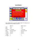
Page 12: ...atient the settings may be restored to the factory defaults These are NIPPY 3 NIPPY Junior IPAP 12cm 12cm EPAP 3cm 3cm Ti back up 1 0 seconds 1 0 seconds Mode Pressure Support Pressure Support Hi Alar...

Page 13: ...perature fault Box Ov Un Tmp Internal temperature below 5 degrees or above 60 degrees Machine covered operated in high ambient temperature or cooling vents blocked Check operational environment Check...

Page 14: ...0 Flt Battery backed up memory access fault Machine failed to access memory probably because of sudden power down No action required Alternative memory location will have been used B Ram1 Flt Battery...

Page 15: ...o other events to log These events are stored in chronological order To view the event log the PC must have NIPPY for Windows software loaded With the software running and the RS232 download lead conn...

Page 16: ...socket screws Stand the ventilator on its base and ease the lid upwards away from the rear panel When the rear of the lid is clear of the rear panel lift it from the left hand side Disconnect the RS23...

Page 17: ...2 Battery Clamp 3 Battery 4 Internal Battery Connector 5 Blower Connector 6 PSU Connector 7 External Battery Connector 8 Cooling Fan Connector 9 Pressure Transducer 10 Flow Transducer 11 Flow Head 12...

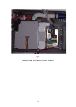
Page 18: ...16 Fig 3 Inside the base with the control board removed...

Page 19: ...Port 2 Board to Board Ribbon Connector 3 Memory Battery Switch 4 Display Connector 5 Display Back light Connector Input 6 Keypad Connector 7 Alarm Sounder 8 Display Back light Connector Output 9 Seco...

Page 20: ...the battery Reverse this procedure to refit The Power Supply Refer to fig 2 Disconnect the 2 way mains connector and the earth terminal Disconnect the 12 way output connector Remove the 4 securing scr...

Page 21: ...Reverse this procedure to refit The Command Board Refer to fig 4 Disconnect the 16 way interconnect lead the Keypad connector the display connector Remove the 4 nuts and washers at each corner of the...

Page 22: ...time and date Page 6 Check battery condition Page 23 Carry out an Electrical Safety Test on ventilator and mains lead Every 2 years Internal battery service life is 2 years under normal conditions Rep...

Page 23: ...If dirt or dust is allowed to build up on the gauze the flow calibration may be affected Inspect the gauze type of flow head when servicing the NIPPY Remove the flow head from the ventilator before cl...

Page 24: ...seconds The disconnection alarm will follow after 10 seconds Occlude the patient outlet A visual and audible alarm will be activated after 10 seconds NIPPY S and ST display a disconnection alarm only...

Page 25: ...e battery if the running time seems low a fault is suspected or to confirm that the battery is good Ensure the battery is fully charged Run the ventilator from the battery until the low battery alarm...

Page 26: ...p the legs of the battery item 10 fig 4 and remove the battery Carefully remove the remaining legs and solder from the pcb Take a new battery and tin the legs This is important as it will clean off an...

Page 27: ...st the blower speed to give a flow reading of 100 l minute on the calibrator 11 Check Flow reading If adjustment is not required proceed to step 13 12 Press the set button to select the flow display U...

Page 28: ...d to the control microcontroller The control micro has its own on board memory If the main micro were to fail the ventilator would continue to function with its last saved settings Command signals fro...

Page 29: ...ower compressor 3 Flow Sensor 4 Outlet connector 5 EVC Port IPPV mode only 6 Breathing Circuit 7 Exhalation Port 8 Patient Connection Port 9 Exhalation Valve IPPV mode only Ventilator System Pneumatic...

Page 30: ...r RS232 Port Microcontroller Alarm Microcontroller Alarm Control Electronics Blower Pressure Transducer Flow Transducer Patient Outlet Port IPPV mode EVC Port and Command Board Power Board NIPPY 3 BLO...

Page 31: ...29 Block Diagram of Nippy 3 Control Board Control Micro EVC Solenoid Blower Drive Pressure Amp Pressure Transducer Flow Transducer Battery Control Charging...

Page 32: ...30...

Page 33: ...31 Circuit Diagrams...

Page 34: ...32...

Page 35: ...33 0901 0901 PCB assembly for Control Board primary side 16 11 07...

Page 36: ...34 0901 0901 PCB assembly for Control Board secondary side 16 11 07...

Page 37: ...35 0756 C 17 02 04 A4 1 1 Component Layout for Nippy 3 Command Board 0756 C...

Page 38: ...36...

Page 39: ...37...

Page 40: ...38...

Page 41: ...39...

Page 42: ...40...

Page 43: ...41...

Page 44: ...42 4 7 0 0 u F...

Page 45: ...Time 0 5 3 0 seconds Back up Rate 6 60 Breaths per minute Type of protection against electric shock Class 1 equipment Degree of protection against electric shock Type B to EN 60601 1 Mode of operation...

Page 46: ...nel 0737B check model LCD Display TRI MODH 0798 Display window B D 3002 SF Blower assembly 0890 U51D1 Blower to outlet tube U62 78 NP Hose Clip Blower 291 694 Outlet adapter Flow head 0909 check colou...

Reviews: