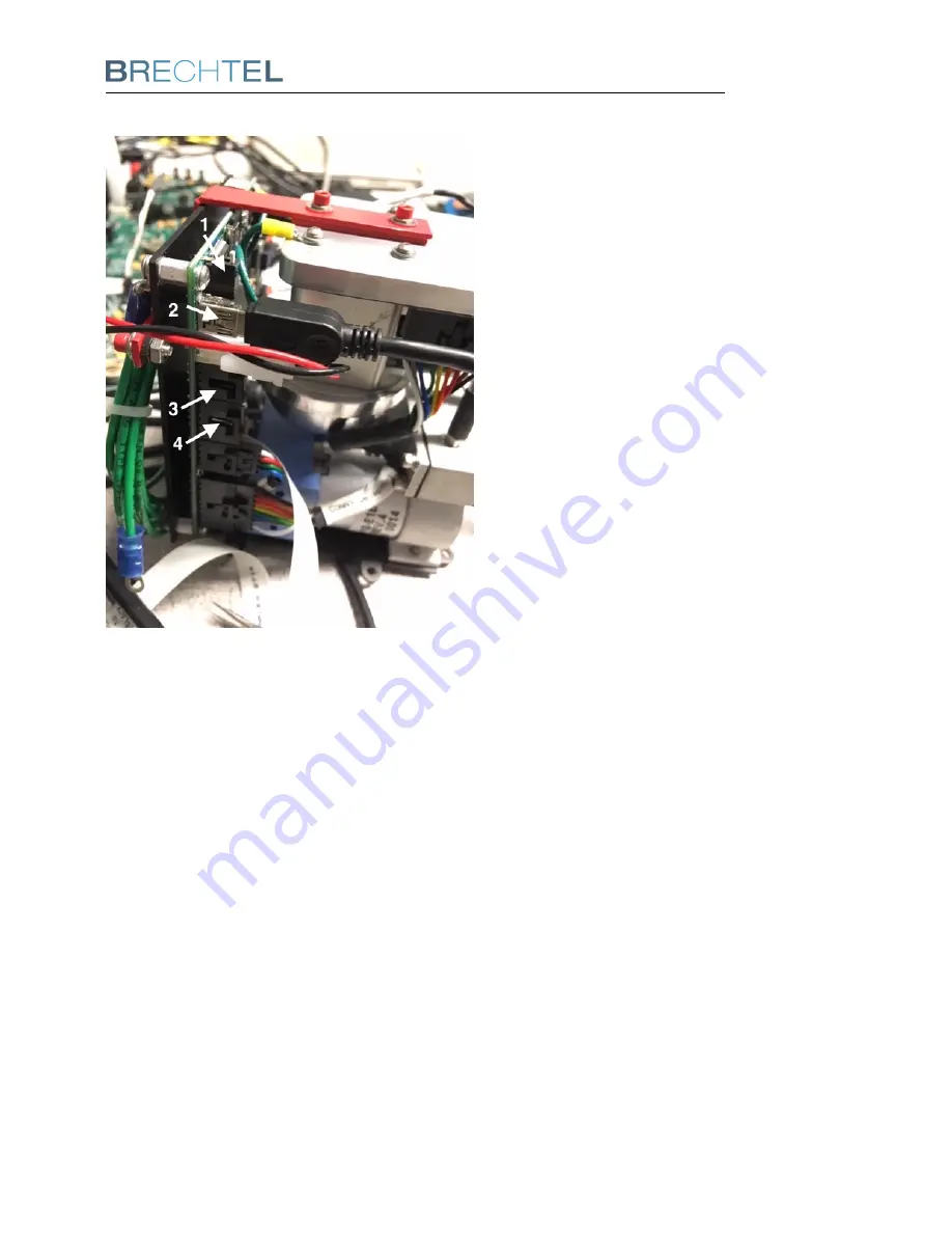
6
System Setup
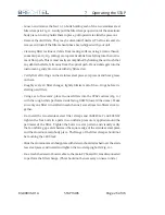
Figure 6:
STAP commu-
nication connections.
Be sure the program/data toggle switch item 1 in figure 6 is in DATA mode (toggled away
from green circuit board) during normal operation. Only toggle the switch to update the
firmware. Switch back to data position after the firmware is updated.
Connect the USB cable provided in the ship kit to the USB mini connector on the main
board, item 2 in figure 6.
The RS232 port item 3 in figure 6 is used to send remote control commands directly to
the STAP from a user computer using the cable provided in the ship kit. The STAP uses a
simple 3 wire RS232 connection. The board connector uses a 3 position C-Grid SL con-
nector. A DB9 adapter is included with each STAP ship kit.
The detailed settings for the serial port: RS232: 8 data bits, 1 stop bit, no parity,
Baud rates: 38.4k, 57.6k, 115.2k and USB with 230k.
83-00036-01A
STAP 9406
Page 19 of 46


