7
Operating the STAP
18. psvolts: Power supply or battery input volts measured (volts)
19. err_rpt: Error report
20. cntdown: Count down timer (sec)
21. fltstat: Filter status
22. flow_sp: Sample flow setpoint (lpm)
23. intervl: Averaging interval (sec)
24. stapctl: Stap control (on off)
7.7 UAV Reader Software
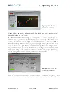
The STAP will interface with the Model 9400 Base Module and UAV Reader Software.
The reader (see Fig. 13) provides a graphical user interface (GUI) allowing timelines of
absorption coefficient data to be viewed in real time on a Windows PC.
The UAV Reader software has been designed to allow multiple instruments to be con-
nected simultaneously so data can logged and instrument performance monitored all
using one user interface. Each instrument has a ”main” tab (display) in the software as
well as a ”details” tab (display) where key operating parameters are shwon. If a par-
ticular instrument is not connected to the reader software then the tab is greyed out.
Multiple STAPs may also be connected to the reader software at the same time, a simple
drop-down menu allows selection of the desired serial number unit.
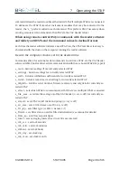
Various instrument settings may also be controlled via the GUI. For example, the STAP
control (On/Off) as well as SD Save settings may be controlled using the buttons shown.
The current filter state, as well as the progression of states through the initialization
process can be controlled via the reader software. If more than one STAP is connected
to the reader, any individual unit can be selected by serial number using the drop down
button in the top left corner. Data may be stored on the PC in addition to the STAP SD
card. The GUI creates the opportunity to remotely control the STAP through external
serial port commands. This feature can be useful during UAV flights or remote location
deployments.
83-00036-01A
STAP 9406
Page 36 of 46


