7
Operating the STAP
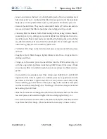
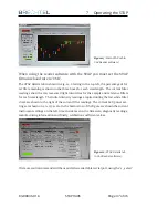
Figure 13:
Main STAP tab in
UAV Reader software).
When using the reader software with the STAP you must set the STAP
firmware baud rate to ’USB’.
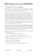
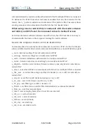
The STAP details tab in shown in Fig. 14. Starting in the top left, the percentage of fil-
ter life remaining is shown in the three boxes for each wavelength. The current filter
readings show the raw measured light intensities for the sample and reference filters
for each wavelength. The initial intensity readings acquired during the last white filter
check are shown to the right of the current filter readings. The current LED power set-
tings are shown on a 0-255 scale. In the bottom row of the figure are shown the current
instrument settings on the left, time and date set in the firmware, diagnostic readings,
manufacturing information and finally, calibration coefficient values.
Figure 14:
STAP Details tab
in UAV Reader software).
If remote control commands will be used via the reader tablet serial port, using the ’s_select’
83-00036-01A
STAP 9406
Page 37 of 46


