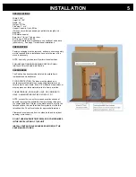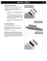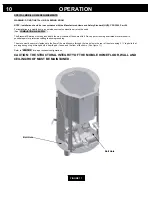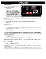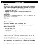
CONTROL PANEL INSTALLATION
Installation of the control panel is required prior to use of the stove.
The diagrams to the right can assist you in this process.
CAUTION:
BE SURE UNIT IS NOT CONNECTED TO ANY
ELECTRICAL POWER SOURCES DURING INSTALLATION OF
CONTROL PANEL.
1.
Install the control panel box onto the brackets at the top
rear of the stove. Use the four screws provided: two for
each side.
2.
Take the end of the wiring harness with the molex
connector and pull it through the back of the control panel
box and plug into the back of the control panel. After the
wiring harness is connected to the control panel, attach
the control panel to the front of the control panel box with
four screws – one in each corner.
3.
Use the remaining four screws to attach the rear panel of
the control panel box. Control panel installation is now
complete.
ELECTRICAL INSTALLATION
This stove is provided with a 6-foot grounded electrical cord
extending from the rear of the stove.
We recommend connecting to a good quality surge protector
that is plugged into a standard three-prong, 120V, 60 Hz
electrical outlet.
Do NOT connect the unit to a GFCI socket.
Voltage variations can lead to serious performance problems. The
Breckwell electrical system is designed for 120V AC with no more
than 5% variation. Breckwell cannot accept responsibility for poor
performance or damage due to inadequate voltage. If connected to
an older, two-prong outlet, a separate ground wire should be run to a
proper ground (refer this to a qualified technician). Always route the
electrical cord so that it will not come in contact with any hot part of
the stove.
INSTALLATION
9
Control Panel Box
Molex Connector
Wiring Harness


