background image

Copyright © 2016 W

atson-Marlow Fluid T

echnology Gr

oup 28-1003208

DuCoNite

® 

and Watson-Marlow Bredel  

are registered trademarks.

APEX / BREDEL PUMP 

Additional information on APEX and Bredel 10, 15 and 20 pumps with bare shaft 
configuration

Summary of Contents for APEX 10

Page 1: ...Copyright 2016 Watson Marlow Fluid Technology Group 28 1003208 APEX BREDEL PUMP Additional information on APEX and Bredel 10 15 and 20 pumps with bare shaft configuration...

Page 2: ...Additional information on APEX and Bredel 10 15 and 20 pumps with bare shaft configuration Original Instructions...

Page 3: ...s to all damage inclusive of without limitation compensating direct indirect or consequential damage loss of data income or profit loss or damage to possessions and claims of third parties Watson Marl...

Page 4: ...ng the support set and Bare Shaft Kit 7 3 2 2 Mounting and aligning the Drive 9 4 MAINTENANCE 4 1 Cleaning 12 4 2 Demounting the Drive 12 4 3 Demounting the Bare Shaft Kit 13 4 4 Disassembling the Bar...

Page 5: ...of components such as pumps motors and inverters is normally not included in this manual However if additional documentation is supplied you must follow the instructions in this additional documentat...

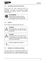
Page 6: ...ely designed for supporting a Bredel or an APEX pumphead and a drive Every other use is not in conformance with the intended ENVIRONMENT Always observe the local rules and regulations with respect to...

Page 7: ...Warranty Conditions Refer to the manual of the pumphead for warranty conditions These conditions are applicable to the bare shaft set as well Damaged parts of the bare shaft set that are returned to t...

Page 8: ...uded The support set consists of a frame an adjustable drive support plate and a coupling guard The bare shaft kit consists of a shaft a hub a bearing and a seal No fasteners are provided for mounting...

Page 9: ...e pump and the pipework 3 2 Installation CAUTION The drive or gearbox and the pump must be aligned within the misalignment limits of the flexible coupling Carry out the alignment of the drive or gearb...

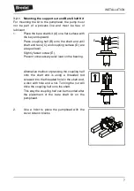
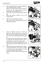
Page 10: ...d coupling surface D are at equal level Slightly fasten screw E Prevent unnecessary axial load on the bearing Alternative method of pressing the coupling half onto the shaft end is using a threaded ro...

Page 11: ...3 teeth coupling end into the pump Make sure the 3 teeth correctly mesh with the holes in the rotor inside the pump 5 Place washers and nuts B 6 Tighten the nuts in at least two crosswise cycles In t...

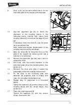
Page 12: ...e height loosen the six sets of fasteners A Move the plate B up or down to the correct position and slightly tighten the fasteners A Check the height and repeat this step if necessary If the height is...

Page 13: ...ent jigs D to check the alignment of the coupling halves in the vertical plane Looking from aside both coupling halves C must touch the horizontal edge of the upper jig If necessary loosen the fastene...

Page 14: ...rt set using a punch and a hammer or a felt tip pen 12 Remove the alignment jigs and use a hoist to remove the drive 13 Drill holes with the correct diameter in the horizontal plate A at the marked pl...

Page 15: ...ing guard and remove the coupling guard B 3 Loosen and remove the fasteners A 4 Move the drive A backward to separate the coupling halves B and C Use a hoist to remove and set aside the drive WARNING...

Page 16: ...a hoist to turn over the pump and put it on blocks 4 Demount the bare shaft kit A by loosening fasteners B When the bare shaft kit is demounted the pumphead will come loose from the support set The p...

Page 17: ...move coupling half B from the shaft by loosening screw A Use a suitable pulling device Do not put axial load on the bearing if it is to be reused 2 Remove retaining ring A 3 Remove key B 4 Push shaft...

Page 18: ...eplaced pliers can be used 4 5 Assembling the Bare Shaft Kit Check the bearing and the seal before reuse If necessary use a new bearing and a new seal 1 Place the hub B on a flat surface with the bear...

Page 19: ...nd seal on the shaft B Put some grease on these surfaces 5 Place shaft C on a flat surface with the key end upward Press bearing B on the shaft with a suitable tool A until it touches the rim 6 Place...

Page 20: ...e flexible coupling 1 Place the bare shaft kit A with the 3 teeth coupling end into the pump and assure that the teeth correctly mesh with the holes in the rotor inside the pump 2 Place washers and nu...

Page 21: ...the spider mesh correctly 4 Place fasteners B to fix the drive on the support set Do not tighten them yet 5 Use two alignment jigs A to check the alignment of the coupling halves in the horizontal pl...

Page 22: ...with the correct torque See section 6 3 Tighten the screws A in the coupling halves with the correct torque See section 6 3 7 Place coupling guard B Place and tighten the fasteners A with the correct...

Page 23: ...tolerances as given in section 6 4 Poor misalignment will shorten the lifetime of the bearing in the bare shaft kit the bearing s in the gearbox and the spider in the flexible coupling Follow the che...

Page 24: ...he pumphead Damaged bare shaft kit bearing Check the alignment See above Check the bearing and the seal and replace if necessary See chapter 4 Rattling or squeaking noise near the gearbox Damaged gear...

Page 25: ...Pos Qty Description Size Material 1 1 Pump support steel 2 1 Gearbox support steel 3 1 Coupling guard steel 4 4 Pin ISO 8750 8 x 24 steel 5 4 Plain washer M5 steel 6 4 Hexagonal head screw M5 x 12 st...

Page 26: ...ling type Pos Qty Description Size Material 1 1 Hub steel 2 1 Joint shaft steel 3 1 Bearing 6006 2RS1 4 1 Radial shaft seal OK NBR RZV 29 x 47 x 10 NBR 5 1 Retaining ring DIN 472 55 steel 6 1 Parallel...

Page 27: ...ations of the flexible couplings which are delivered as part of a complete pump based on the bare shaft solution Metric thread size Torque Nm Drill diameter mm M5 6 6 M6 10 7 M8 25 9 M10 50 11 M12 85...

Page 28: ...tside of the packaging containing the item s The sender of the item s is responsible for cleaning and decontaminating of the item s before returning them in such way that it is safe for the receiver t...

Page 29: ...03208 TS16 025 Watson Marlow Bredel B V P O Box 47 NL 7490 AA Delden The Netherlands Telephone 31 0 74 3770000 Fax 31 0 74 3761175 E mail Bredel wmftg com Internet www wmftg com 2017 Watson Marlow Bre...

Page 30: ...arlow Bredel B V accepts no liability for any error it contains and reserves the right to alter speci cations without prior notice All mentioned values in this document are values under controlled cir...

Reviews: