MAINTENANCE
21
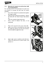
3.
Slide the drive (B) toward the pumphead.
Make sure that the coupling halves (A) and the
spider mesh correctly.
4.
Place the fasteners (A). Do not tighten them.
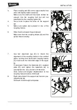
5.
Use two alignment jigs (D) to check the
alignment of the coupling halves (C) in the
horizontal plane. Looking from above both
coupling halves (C) must touch the edge of both
jigs.
If necessary move the drive (E) over the plate
(B) to accomplish this.
Axial, radial and angular displacement of the
coupling halves must be minimised.
6.
Tighten the fasteners (A) to fix the drive to the
support set with the correct torque. See section
6.3.
7.
Place the coupling guard (B).
Tighten the fasteners (A) with the correct
torque. See section 6.3.
8.
Connect the drive to the power supply.
A
B
C
D
C
E
B
A
B
A
Summary of Contents for BREDEL PUMP Series
Page 2: ...Additional Information on Bredel 40 pump with bare shaft configuration Original Instructions...
Page 33: ...30...
Page 34: ...31...
Page 36: ...33...


