background image

 Verifying Proper Operation

SU-I/ID Installation Manual

18

BreezeACCESS MMDS Series

6.  VERIFYING PROPER OPERATION

After completing the installation, and after connecting the unit to the AC mains,
the system starts operation. To verify proper operation, view the LED panel
located on the front panel of the unit. Table 6-1 lists the various LED states.

Table 6-1.  SU-I LEDs

Name

Description

Functionality

PWR

Power supply

On – After successful power up
Off – Power off

WLNK

Wireless Link
Activity

Blinking – Receiving packets from the wireless
link
Off – no reception of packets from the wireless
link

ETH

Ethernet activity

Blinking – Reception of data from Ethernet LAN

Off – No reception of data from Ethernet LAN

QLT

Quality of
received RF
signal

Very low quality reception or not
synchronized with Access Unit, less than
-81 dBm

Low quality reception (usually enabling
1Mbps traffic) from -81 to -77 dBm

Medium quality reception (usually
enabling 2 Mbps traffic) from -77 to -65
dBm

High quality reception (usually enabling
3 Mbps traffic) greater than -65 dBm

6.1  Verifying Data Connectivity

From the user’s PC or from a portable PC connected to the unit, Ping the unit or
try to connect it to the Internet.

Summary of Contents for BreezeACCESS

Page 1: ...BreezeACCESS MMDS Indoor Subscriber Units SU I ID MMDS Series Installation Manual July 2000 Cat No 213099 ...

Page 2: ...from date of purchase During this warranty period the Company will at its option either repair or replace products that prove to be defective For warranty service or repair the product must be returned to a service facility designated by the Company Authorization to return products must be obtained prior to shipment The buyer shall pay all shipping charges to the Company and the Company shall pay ...

Page 3: ...ound to comply with the limits for a class A digital device pursuant to Part 15 of the FCC rules These limits are designed to provide reasonable protection against harmful interference when the equipment is operated in a commercial environment This equipment generates uses and can radiate radio frequency energy and if not installed and used in accordance with the instruction manual may cause harmf...

Page 4: ...of the instrument 100 250 VAC 50 60 Hz Radio The instrument transmits radio energy during normal operation To avoid possible harmful exposure to this energy do not stand or work for extended periods of time in front of its antenna The long term characteristics or the possible physiological effects of Radio Frequency Electromagnetic fields have not been yet fully investigated Antenna Installation a...

Page 5: ...4 2 4 4 Antenna Polarization 5 2 4 5 Antenna Seal 5 2 4 6 Lightning Protection 5 2 5 Wall Mounting the Unit 6 2 6 Connecting Antenna s to the Units SU ID units only 8 2 7 Connecting the Unit to the Power Supply and to the CPE 9 3 CONFIGURING SYSTEM PARAMETERS 10 3 1 Getting Started with the Local Terminal 10 3 2 Configuration Parameters 12 3 3 Reset Unit 14 4 ALIGNING THE ANTENNA 15 4 1 Aligning t...

Page 6: ...nnectivity 18 7 SPECIFICATIONS 19 7 1 Radio 19 7 2 Data Communication 19 7 3 Configuration and Management 20 7 4 Interfaces 20 7 5 Electrical 20 7 6 Mechanical 20 7 7 Environmental 20 7 8 Standards Compliance General 21 APPENDIX A AL 1 Lightning Arrestor 22 APPENDIX B USING TELNET 24 APPENDIX C MMDS CHANNELS AND FREQUENCIES 25 ...

Page 7: ...llation Manual Table of Figures Figure 2 1 Wall Mounting the Unit 7 Figure 2 2 Wall Mounting Plate 7 Figure 2 3 Tightening the Cable s to the Connector s 8 Figure 3 1 Main Menu 11 Figure 3 2 Basic Configuration Menu 13 Figure A 1 AL 1 Connection Block Diagram 22 ...

Page 8: ......

Page 9: ...f Subscriber Units comprises compact units that are designed for indoor installation SU I units include two 2dBi integrated antennas SU ID units have two RF connectors for detached diversity antennas Detached antennas can be installed either indoors or outdoors depending on the specific site conditions The SU I ID MMDS is available in two frequency bands SU I ID MMDSa products operate in the 2 500...

Page 10: ...ithout antennas A 5 VDC universal power supply transformer Mounting bracket for wall or ceiling installation A torque key for antenna connectors SU ID units 2 2 Other Required Items The following items must be available for the installation Antenna s and RF cable s for SU ID units according to specific installation requirements A PC with terminal emulation program A monitor cable supplied with eac...

Page 11: ...Section 2 7 6 Configure the basic system parameters as described in Section 3 7 Align the antenna s for optimal connectivity and configure the Maximum Data Rate if applicable as described in Chapters 4 and 5 8 Check the functionality of the unit as described in Chapter 6 2 4 Installation Guidelines This section describes the installation guidelines and the various considerations that must be taken...

Page 12: ...n path Install outdoor antennas high enough to avoid any obstacles which may block the signal Position the antennas clear of metal furniture and away from moving metal objects such as metal fans or doors For best performance position the antennas clear of radiation sources that emit in the 2 5 2 7 GHz frequency band such as microwave ovens 2 4 3 Antenna Diversity In applications where no multipath...

Page 13: ...tennas are not suitable for use in outdoor installations 2 4 6 Lightning Protection Lightning protection is designed to protect people property and equipment by providing a path to ground for the lightning s energy The lightning arrestor diverts the strike energy to ground through a deliberate and controlled path instead of allowing it to choose a random path Lightning protection for a building is...

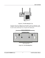
Page 14: ...uthorities Failure to do so may void the BreezeACCESS Product Warranty and may expose the end user to legal and financial liabilities BreezeCOM and its resellers or distributors are not liable for injury damage or violation of government regulations associated with the installation of detached antennas 2 5 Wall Mounting the Unit Use the supplied brackets for wall mounting to install the unit on a ...

Page 15: ...lots have been added to the wall mounts to allow for unobtrusive cable installation These slots should be used to fasten cables coming out of the unit to the wall mounts eliminating loose or tangled cable installations Convenience Mounting Slots Unit Mounting Slots Cable Fastening Slots Figure 2 2 Wall Mounting Plate ...

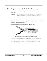
Page 16: ...age to the cable connectors Use the included torque key to tighten the cable s to the connector s on the side of the SU I unit The key is designed to prevent over tightening of the screws and protects the connectors from damage Tighten the cable s to the connector s using the torque key Figure 2 3 Tightening the Cable s to the Connector s If excessive pressure is applied to tighten the screws the ...

Page 17: ...ower transformer included with the unit 1 Plug the output jack of the power transformer into the DC input jack located on the rear panel of the unit 2 Connect the supplied universal power transformer to a power outlet 110 220VAC 3 Use a straight Ethernet 10BaseT cable to connect a PC SU I ID or a hub SU I ID 8D or SU I ID BD to the Ethernet port marked UTP located on the rear panel of the unit ...

Page 18: ...formation refer to Appendix B 3 1 Getting Started with the Local Terminal 1 Connect one end of the Monitor cable to the MON jack on the rear side of the unit Connect the second end of the cable to the COM port of the terminal The COM port connector on the Monitor cable is a 9 pin D type plug 2 Run a terminal emulation program e g ProComm or Windows HyperTerminal using the following setup Baud rate...

Page 19: ...ance with the access level For users with read only access rights only the Info Screens option is displayed Users with this access level cannot access the Unit Control Basic Configuration Site Survey and Advanced Configuration menus For users with Installer access rights the first four menu items Info Screens Unit Control Basic Configuration and Site Survey are displayed Users with this access lev...

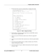
Page 20: ...g 2 in the Info Screens menu to view the Basic Configuration parameters 3 2 Configuration Parameters The following system parameters must be configured for each specific installation ESSID IP Address Subnet Mask Default Gateway Address Frequency Offset Hopping Band Flexible sub bands Definition if Flexible Hopping was selected in the Hopping Band menu Transmit Antenna Note You must select Reset Un...

Page 21: ...bands Definition G Transmit Antenna P Power Level S Show Basic Configuration BreezeACCESS Figure 3 2 Basic Configuration Menu 2 From the Basic Configuration menu type 4 to access the ESSID selection screen Enter the required ESSID 3 Type 1 to access the IP Address selection screen Enter the required IP address 4 Type 2 to access the Subnet Mask selection screen Enter the required subnet mask 5 Typ...

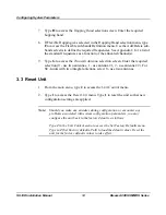
Page 22: ...ter the required selection 0 use two antennas 1 use antenna 1 2 use antenna 2 For SU I units with two integral antennas select 0 use two antennas 3 3 Reset Unit 1 From the main menu type 2 to access the Unit Control menu 2 Type 1 to access the Reset Unit menu Type 1 to reset the unit so that new configuration settings are applied Note Should you make any mistakes during configuration or encounter ...

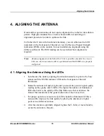
Page 23: ...he Access Unit you wish to associate with is operational and the ESSID was properly configured 4 1 Aligning the Antenna Using the LEDs 1 Synchronize the units by aligning the antenna manually to point to the base station until the WLNK indicator LED on the front panel of the unit illuminates 2 Rotate the antenna left and or right until you reach the point of signal quality reading on the quality Q...

Page 24: ... average RSSI for these frames 3 Rotate the antenna left and or right until you reach the point of maximum RSSI reading Make sure that at all times the front of the antenna faces the general direction of the Base Station 4 For proper operation the RSSI reading should be at least 52 units When the maximum reading is less than 52 units try to improve it by placing the antenna at a higher point or in...

Page 25: ... 3 Mbps is too high and the data rate of the unit should be configured accordingly 2 From the main menu type 3 to access the Basic Configuration menu Type 5 to access the Maximum Data Rate menu L Type 3 3Mbps if the RSSI reading is higher than 76 units LL Type 2 2Mbps if the RSSI reading is between 66 to 76 units LLL Type 1 1Mbps if the RSSI reading is lower than 66 units 3 Reset the unit for the ...

Page 26: ...king Receiving packets from the wireless link Off no reception of packets from the wireless link ETH Ethernet activity Blinking Reception of data from Ethernet LAN Off No reception of data from Ethernet LAN QLT Quality of received RF signal Very low quality reception or not synchronized with Access Unit less than 81 dBm Low quality reception usually enabling 1Mbps traffic from 81 to 77 dBm Medium ...

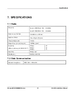
Page 27: ... B MMDSb 2 596 2 686GHz Radio Access Method FH CDMA or TDMA Operation Mode Time Duplex Division Channel Bandwidth 2 MHz Output Power at antenna port 19dBm typical Sensitivity dBm at antenna port BER 1E10 6 1Mbps 2Mbps 3Mbps 89 82 73 Data Rate 3Mbps max Modulation Multilevel GFSK 7 2 Data Communication Standard Compliance IEEE 802 3 CSMA CD ...

Page 28: ...MIB Private MIBs Accounting RADIUS compatible client Security Authentication and filtering Software upgrade TFTP download 7 4 Interfaces RF Antenna 2 x SMA jacks Ethernet 10Base T RJ 45 Monitor 3 pin low profile Power DC socket for a power transformer 7 5 Electrical External power Supply 100 250 VAC 50 60 Hz 0 5 A Input voltage 5VDC 7 6 Mechanical Without antenna and power supply 13cm x 8 6cm x 3c...

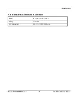
Page 29: ...Specifications BreezeACCESS MMDS Series 21 SU I ID Installation Manual 7 8 Standards Compliance General EMC FCC part 15 FCC part 21 Safety UL 1950 Environmental GR 63 CORE Bellcore ...

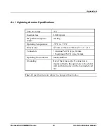
Page 30: ...riginating from lightning or EMP The AL 1 is gas tube based and is not radioactive The gas discharge tube can sustain several transients if the time period between transients is sufficient to allow the tube to cool down Figure A 1 AL 1 Connection Block Diagram One of the female type N connectors is mounted directly through a hole in the shelter wall and held in place with a lockwasher and nut ...

Page 31: ...ng Operating Temperature 55 C to 70 C Dimensions 67 5mm x 25mm x 25mm 2 7 x 1 x 1 Connectors Antenna Port N type Female Equipment Port N type Female Operating Environment Indoor Outdoor Grounding One of the female type N connectors is mounted directly through a hole in the shelter wall and held in place with a lockwasher and nut Note All specifications are subject to change without notice ...

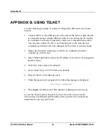
Page 32: ...nit to be managed via the wired or wireless media 2 Make sure that the IP parameters of the PC are configured to enable connectivity with the unit 3 Run a Telnet application and use the IP address of the unit to be managed as the Host Name 4 Set Port to Telnet this is the default 5 Set Terminal Type to VT100 this is the default 6 Enter the Service Provider password 7 When the password is recognize...

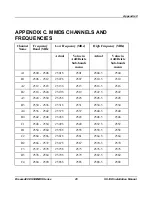
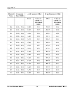
Page 33: ...512 2507 5 2507 2510 5 2510 A2 2512 2518 2513 5 2513 2516 5 2516 B2 2518 2524 2519 5 2519 2522 5 2522 A3 2524 2530 2525 5 2525 2528 5 2528 B3 2530 2536 2531 5 2531 2534 5 2534 A4 2536 2542 2537 5 2537 2540 5 2540 B4 2542 2548 2543 5 2543 2546 5 2546 C1 2548 2554 2549 5 2549 2552 5 2552 D1 2554 2560 2555 5 2555 2558 5 2558 C2 2560 2566 2561 5 2561 2564 5 2564 D2 2566 2572 2567 5 2567 2570 5 2570 C3...

Page 34: ...8 2603 5 2603 2606 5 2606 E2 2608 2614 2609 5 2609 2612 5 2612 F2 2614 2620 2615 5 2615 2618 5 2618 E3 2620 2626 2621 5 2621 2624 5 2624 F3 2626 2632 2627 5 2627 2630 5 2630 E4 2632 2638 2633 5 2633 2636 5 2636 F4 2638 2644 2639 5 2639 2642 5 2642 G1 2644 2650 2645 5 2645 2648 5 2648 H1 2650 2656 2651 5 2651 2654 5 2654 G2 2656 2662 2657 5 2657 2660 5 2660 H2 2662 2668 2663 5 2663 2666 5 2666 G3 2...

Reviews: