ENGLISH
28
HeliX
2
OCCUPANT RESTRAINTS INSTRUCTION:
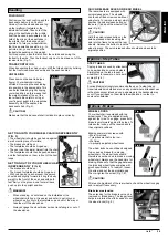
1. The pelvic restraint belt must be worn low across the front of the
pelvis so that the angle of the pelvic belt is within the preferred zone
of 30 to 75 degrees to the horizontal.
A steeper (greater) angle within the preferred zone is desirable i.e.
closer to, but never exceeding 75degrees. (Fig C)
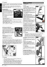
2. The upper torso restraint belt must fit over the shoulder and
across the chest as illustrated Fig d and e
Restraint belts must be adjusted as tightly as possible consistent
with user comfort.
Restraint belt webbing must not be twisted when in use.
The upper torso restraint belt must fit over the shoulder and across
the shoulder as illustrated in Fig D and E.
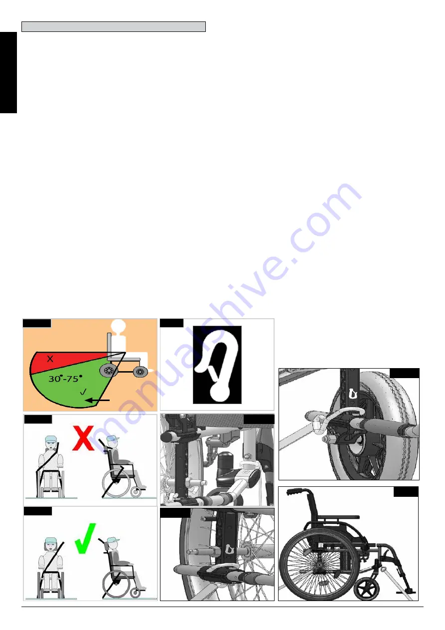
3. The attachment points to the chair are the inner front side frame
just above the castor, and the rear side frame. The straps are fitted
around the side frames at the intersection of the horizontal and
vertical frame tubes. (See Figs G - K)
4. The tie down symbol (Fig F) on the wheelchair frame indicates
the position of the wheelchair restraint straps. The straps are then
tensioned after the front straps have been fitted to secure the
wheelchair.
USER WEIGHT LESS THAN 22 kg (48 lb 8.0 oz)
When the user being transported is a child, less than 22Kg mass
and the vehicle involved has less than eight (8) seated passengers
it is recommended that they be transferred to an UNCE Regulation
44 compliant child restraint system (CRS).
This type of restraint system provides a more effective occupant
restraint system than the conventional 3 point occupant restraint
system and some CRS systems also include additional postural
supports to assist in maintaining the position of the child when
seated.
Parents or care providers may consider the option, in some
circumstances, for their child is to remain in their wheelchair whilst in
transport due to the level of posture control and comfort provided by
the set up in the wheelchair.
We would recommend in such circumstances that a risk assessment
be carried out by your healthcare professional and relevant
competent persons.
POSITIONING OF WHEELCHAIR TIE DOWN RESTRAINTS
ON WHEELCHAIR:
1. Location of the front and rear tie down labels (Fig. G-H-I).
2. Position of the front, (Fig.G) and rear, (Fig.H-I), wheelchair tie
down restraint and the tie down label.
3. Side view of tie down straps, (Fig.J).
Fig.D
Fig.E
Fig.C
PREFERED
ZONE
Fig.F
Transportability
Fig.G
Fig.
J
Fig.
H
Fig.
I


