ENGLISH
30
HeliX
2
DRUM BRAKES
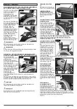
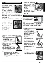
Drum brakes permit safe and
convenient braking for an attendant.
They can also be set with the aid of a
locking lever (1) to prevent rolling.
The lever must snap audibly into
place.
Drum brakes are not influenced by air
pressure inside the tyres, (Fig.10).
CAUTION!
•
Drum brakes must only be adjusted
by authorised dealers
•
Always operate the two brakes simultaneously to guarantee the
control of the driving direction!
•
Drum brakes can only be used as a dynamic brake to stop the
wheelchair while driving.
•
Always engage the wheel locks to secure the wheelchair during a
short or long stop, or for transfer.
Fig. 10
1
ONE-HAND OPERATION
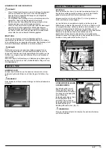
Your wheelchair is equipped with two sets
of wheel locks that can be operated from
either the left or the right side. They are
applied directly against the tyres. To
engage, press the brake lever forward
against the stops (Fig. 11). To release the
locks, pull the lever back to its original
position.
Braking power will decrease with:
•
Worn tyre tread
•
Tyre pressure that is too low
•
Wet tyres
•
Improperly adjusted wheel locks.
The wheel locks have not been designed to be used as brakes for
a moving wheelchair. The wheel locks should therefore never be
used to brake a moving wheelchair. Always use the hand-rims for
braking. Make sure that the gap between the tyres and wheel locks
complies with given specifications. To readjust, loosen the screw
and set the appropriate gap. Then re-tighten the screw (see the
page on torque), (Fig. 12).
Fig. 12
CAUTION!
•
After each adjustment of the rear wheels, check the wheel
lock gap and re-adjust if necessary.
•
Mounting the wheel lock too close toward the wheel will result
in a higher effort to operate. This might cause the brake lever
extension to break! Leaning onto the brake lever extension
while transferring will cause the lever to break! Splashing
water from tyres might cause the wheel lock to malfunction.
Fig. 11
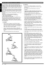
FOOTPLATES:
The footplates can be flipped up to make it easier to transfer to/from
the chair.
Lower leg length:
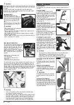
For users with longer legs, the leg
support can be lowered to the appropriate
level by using the screws (1). Loosen the
screws, push the tubes to the desired
position and then re-tighten the screws
(see section on torque).
There must always be a minimum gap of
2.5 cm between the footplates and the
ground (Fig. 13).
Angle-adjustable footboard
This can be adjusted to alter the angle to
the ground. Release screw, pull it
inwards, set the desired angle and then
push it on. After making the adjustment,
re-tighten the screw.
Make sure that after any
adjustment work, all screws are tightened
correctly (see the page on torque).
Ensure that you maintain the minimum
gap to the floor (2.5 cm) (Fig. 14).
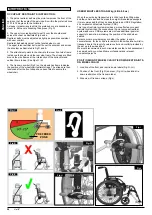
FOOTRESTS AND LATCH
The legrests can be swung inwards under
the seat sling or outwards. When fitting
the legrests, the footrests must be
pointing inwards or outwards. Then rotate
the legrest inwards, until it locks into
place. To remove, pull the lever (1), swing
the footplate inwards or outwards and
then lift the legrest out. Make sure that
the legrest is locked into place correctly,
(Fig 15).
CAUTION!
•
The legrests must not be used to lift or to carry the wheelchair.
•
When getting on or off the wheelchair, do not use the
footboards. These should be flipped up beforehand or the
footrest should be swung to the outside as far as possible.
OPTION ELEVATING LEG REST
(Fig 16-18)
To remove, pull the lever (1), swing the
footplate outwards and then lift the leg
rest out.
HEIGHT ADJUSTMENT:
The lower leg length can be adjusted
infinitely by releasing the screw (2).
Adjust the suitable height and tighten the
screw again.
CAUTION!
The distance between the footplate
and the ground must be at least 40
mm.
ANGLE ADJUSTMENT:
Press the lever (3) downward with one
hand while supporting the leg rest with
the other hand to take the load off. When
a suitable angle is achieved, let go of the
lever and the legr est will lock into one of
the preset positions.
Options - Footplates
Fig. 14
FIG. 13
1
FIG. 16
1
2
FIG. 17
3
FIG. 18
CAUTION!
Mounting the wheel lock too close towards the wheel will result in a
higher effort to operate. This might cause the brake lever extension
to break!
Leaning onto the brake lever extension while transferring will
cause the lever to break! Splashing water from tyres might cause
the wheel lock to malfunction.
FIG.15
1


