11
UniX
2
en
GL
ish
options - footplates
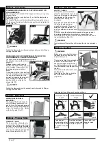
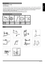
footpLates:
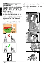
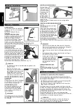
The footplates can be flipped up to make
it easier to transfer to/from the chair.
Each assembly weighs 1.0kg
Lower LeG LenGth:
For users with longer legs, the leg
support can be lowered to the
appropriate level by using the screws (1).
Loosen the screws, push the tubes to the
desired position and then re-tighten the
screws (see section on torque). There
must always be a minimum gap of 2.5
cm between the footplates and the
ground, (Fig.11).
footrests anD Latch
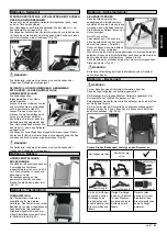
The legrests can be swung inwards
under the seat sling or outwards. When
fitting the legrests, the footrests must be
pointing inwards or outwards. Then
rotate the legrest inwards, until it locks
into place. To remove, pull the lever (1),
swing the footplate inwards or outwards
and then lift the legrest out. Make sure
that the legrest is locked into place
correctly, (Fig.12).
caution!
The legrests must not be used to lift or to carry the wheelchair.
•
When getting on or off the wheelchair, do not use the footboards.
•
These should be flipped up beforehand or the footrest should be
swung to the outside as far as possible.
option eLeVatinG LeGrest
(Fig 13-15)
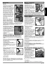
To remove, pull the lever (1), swing the
footplate outwards and then lift the
legrest out.
heiGht aDjustMent:
The lower leg length can be adjusted
infinitely by releasing the screw (2).
Adjust the suitable height and tighten the
screw again.
caution!
The distance between the footplate
and the ground must be at least 40
mm.
fiG. 12
1
fiG. 13
1
fiG. 11
1
aDjustinG the caLf paD
(Fig 16).
The calf pad can be adjusted as
follows:
Height: Open bolt (4) and move the
clamping piece to the desired
position. By rotating the clamping
piece also the angle can be
adjusted.
Depth: Open bolt (5) and move the
calf pad into the desired position.
Width: Open bolt (5) and position the
spacers (6) behind the pad, to get
the desired position.
warninG!
Keep hands clear of the adjustable mechanism between the
•
frame and the movable parts of the foot rest, while elevating or
lowering the footrest.
Always make sure that the fasteners are secure.
•
The foot rests must not be used to lift or to carry the
•
wheelchair.
Risk of trapping fingers! When moving the foot rest up or
•
down, do not put your fingers in the adjusting mechanism
between the moving parts of the foot rest.
aMputee support
(Fig.17).
The Amputee Support can be
adjusted in every direction as
required.
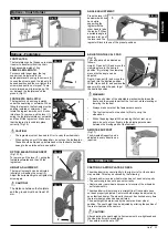
castors, castor pLates, forKs
The wheelchair may veer slightly to the right or left, or the castors
may wobble. This may be caused by the following:
• Forward and/or reverse wheel motion has not been set properly.
• The castor angle has not been set correctly.
• Castor and/or rear wheel air pressure is incorrect; the wheels do
not turn smoothly.
The wheelchair will not move in a straight line if the castors have
not been properly adjusted. Castors should always be adjusted by
an authorised dealer. The wheel locks must be checked every time
the rear wheel position has been altered.
The seat height is determined by the castor and rear wheel
position. The seat height can be adjusted by altering the position of
the rear wheels and the castors
caution!
After adjusting the seat height, all screws must be re-tightened and
the wheel lock must be readjusted.
The castors must be set at 90
°
2
fiG. 14
fiG. 16
4
5
6
fiG. 17
options - castors
options - crutch holder
fig. 9
fig. 10
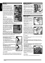
anGLe aDjustMent:
Press the lever (3)
downward with one
hand while
supporting the
legrest with the
other hand to take
the load off. When
a suitable angle is
achieved, let go of
the lever and the
legrest will lock into one of the preset positions.
3
fiG. 15


