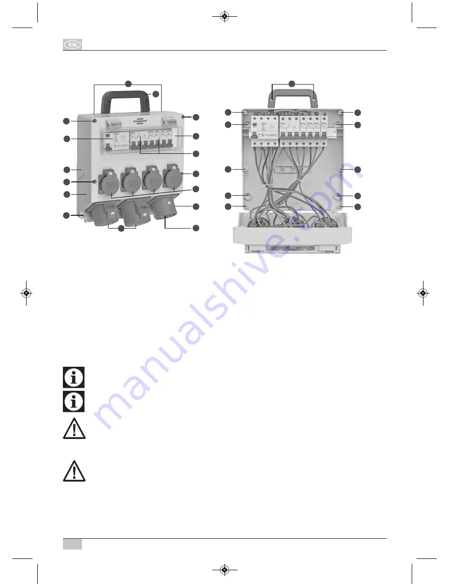
Distribution box layout
Fig. A: Example of 32 A distribution box
Fig. B: Example of 32 A distribution box
���
Bottom of housing
���
CEE socket
���
Top of housing
���
Schuko socket
���
Carry handle
쐅
Housing screws
���
Window
쐈
Mounting holes
���
Residual current device
쐉
Threaded holes
���
Protective equipment
씈
Connection socket
���
Pre-assembled cable feeds
Installation and commissioning
The activities described in this chapter may only be performed by a qualified electrician!
The device is intended for vertical wall mounting only.
The proper operating position is with the hinged lids of the sockets opening upwards.
WARNING
Connecting the device to a supply cable with insufficient cable cross-section and/or an
insufficient upstream fuse could result in a fire which may cause injuries or lead to an overload
and damage the device. Please observe the information on the name plate!
DANGER
Working at live parts may cause severe or fatal injuries.
– De-energize the supply cable of the device for installation and mounting work.
– Secure the system against unintended re-activation of the supply voltage by other persons.
– Ensure that the supply cable is de-energized before starting installation or mounting work.
– Ground and short-circuit.
– Cover or fence off adjoining live parts.
11
9
12
12
11
11
11
11
12
12
12
12
2
10
1
3
7
9
8
10
10
10
5
4
6
10
10
13
WV 4/16A IP44 · WV 4/32A IP44
14
089417 BA_Wandverteiler WV 4_16 4_32.qxp 07.02.18 15:31 Seite 14


