background image

13 | Imprint

18 / 21

IM_4670350_de_en_BRESSER_v1016

13 Using eyepieces

The magnification range depends on the focal length of the telescope and the eyepieces*. The magni-
fication can be varied by changing the eyepieces.

Example:

Focal length telecope : Eyepiece focal length = Magnification
350mm : 20mm = 17.5x

Use an eyepiece* with higher focal length (= lower magnification) when starting an observation.

(*depending on the model, it can be part of the content)

14 Using an Amici prism

An Amici prism* will be attached to the telescope between the eyepiece holder and the eyepiece*. It
allows for an image reversal to an upright and lateral image.

(*depending on the model, it can be part of the content)

15 Moving the tripod head

NOTICE

Tighten locking screws/rings only by hand.

Tighten locking screws/rings only by hand. Rings and threads can break when overtighten them!

1. Loosen the fixing screw for horizontal movement to move the tripod head to the right or to the left.

2. Tighten the fixing screw by hand to set the tripod in current horizontal position.

3. Loosen the fixation for vertical movement by turning the handle counterclockwise. Tilt the tripod

head up and down.

4. Turn the handle clockwise to to set the tripod head in current vertical position.

5. Loosen the fixing screw for the tripod tilt plate to tilt the the attached optics sidewards for a viewing

position up to 90 degrees.

6. Tilt the tilt plate to the right and tighten the fixing screw by hand to set the tilt plate in current posi-

tion.

16 Adjusting the viewfinder

1. Insert an eyepiece with higher focal length into the diagonal mirror (for refracting telescopes) or

directly into the eyepiece holder (for reflecting telescopes).

2. With the telescope, target on a specific object (e.g. house gable, church spire or otherwise) at a

distance of approx. 300 meters.

3. Look through the eyepiece and align the telescope until the object is visible in the middle of the

eyepiece's field of view.

4. Look through the viewfinder and align it by turning the adjustment screws until the object is visble

in the middle of the viewfinder's hair cross.

5. The adjustment of the viewfinder is completed if the image is visible in the middle of the viewfinder

and the eyepiece in the same way.

Summary of Contents for 4670350

Page 1: ...anleitung DE Information d utilisateur FR Gebruikersinformatie NL Información de usuario ES Informazione degli utenti IT Instruction Manual EN Teleskop Telescope Télescope Telescoop Telescopio Classic 70 350 Art No 4670350 ...

Page 2: ...t le code QR ou le lien correspondant NL Bezoek onze internetpagina via de volgende QR code of weblink voor meer informatie over dit product of de beschikbare vertalingen van deze gebruiksaanwijzing ES Desearía recibir unas instrucciones de uso completas sobre este producto en un idioma determinado Entonces visite nuestra página web utilizando el siguiente enlace código QR para ver las versiones d...

Page 3: ...dungen 6 7 Lieferumfang 6 8 Teileübersicht 6 9 Standortwahl 7 10 Stativ aufstellen 7 11 Optiktubus auf Stativ montieren 8 12 Zubehörteile anbringen 8 13 Verwendung von Okularen 9 14 Verwendung eines Amici Prismas 9 15 Stativkopf bewegen 9 16 Justieren des Sucherfernrohrs 9 17 Vor der Beobachtung 10 18 Beobachtung 10 19 Fehlerbeseitigung 10 20 Reinigung und Wartung 10 21 Entsorgung 11 22 Garantie 1...

Page 4: ...waren mar ken und oder patentrechtlich geschützt 2 Eigenschaften Achromatische Optik nach Fraunhofer Vergütete Objektivlinsen Solider Tubus aus Metall Höhenverstellbares Fotostativ mit Handführung Tauschutzkappe 3 Zu dieser Anleitung HINWEIS Diese Bedienungsanleitung ist als Teil des Gerätes zu betrachten Lesen Sie vor der Benutzung des Geräts aufmerksam die Sicherheitshinweise und die Bedienungsa...

Page 5: ...m die Entstehung von Bränden zu vermeiden Setzen Sie das Gerät speziell die Linsen keiner direkten Sonneneinstrahlung aus Durch die Lichtbündelung könnten Brände verursacht werden HINWEIS Gefahr von Sachschäden Bei unsachgemäßer Handhabung können das Gerät und oder die Zubehörteile beschädigt werden Verwenden Sie das Gerät deshalb nur entsprechend den nachfolgenden Sicherheitsinformationen Bauen S...

Page 6: ...5 9 11 12 13 14 16 18 17 19 22 21 21 23 24 25 26 20 Abb 1 Produktabbildungen 7 Lieferumfang Optik mit Tubus OTA A Stativ B 3 Okulare C Amici Prisma D Sucherfernrohr E 8 Teileübersicht 1 Tauschutzkappe 2 Objektivlinse 3 Fixierschraube Halterung Sucherfernrohr 4 Halterung Sucherfernrohr 5 Okularauszug ...

Page 7: ...ntergrund muss eben und stabil sein Nicht aus geschlossenen Räumen heraus beobachten Teleskop und Zubehör ca 30 Minuten vor Be obachtungsbeginn an den gewünschten Standort stellen damit ein Temperaturausgleich gewährleis tet ist 10 Stativ aufstellen 1 Arretierungsring für die Stativspinne lösen 2 Stativbeine langsam nach außen ziehen bis Stativspinne vollständig geöffnet ist 3 Arretierungsring für...

Page 8: ...ivkopfplatte am Optiktubus zu befestigen Darauf achten dass der Zap fen zur Fixierung in die entsprechende Bohrung greift 4 Den Arretierungshebel in Position FREE drücken und den Optiktubus mit der montierten Stativ kopfplatte in die Halterung einsetzen Darauf achten dass die Objektivlinse in die entgegengesetz te Richtung zum Führungsgriff zeigt 5 Arretierungshebel in Position LOCK drücken 12 Zub...

Page 9: ...ixierschraube handfest anziehen um den Kopf in der gegenwärtigen horizontalen Position fest zusetzen 3 Führungsgriff entgegen dem Uhrzeigersinn drehen um die Fixierung für die vertikale Bewegung zu lösen und den Stativkopf nach oben oder unten zu kippen 4 Führungsgriff im Uhrzeigersinn drehen um den Kopf in der gegenwärtigen vertikalen Position fest zusetzen 5 Für eine um 90 gedrehte Beobachtungsp...

Page 10: ...driger Brenn weite kann die Vergrößerung gesteigert werden 19 Fehlerbeseitigung Problem Fehler Mögliche Lösung Kein Bild Schutzkappen entfernen Okular mit geringerer Vergrößerung wählen Unscharfes Bild Bildschärfe mittels Fokusrad einstellen Keine Scharfeinstellung möglich Temperaturausgleich abwarten Schlechtes Bild Nicht durch Glasscheiben beobachten Objekt im Sucher aber nicht im Teleskop sicht...

Page 11: ...dung kommen Dies ist kein Mangel Lassen Sie in diesem Fall das Gerät bei Zimmertemperatur einige Zeit akklimatisieren so dass die Restfeuchtigkeit abgebaut werden kann Nachdem die Restfeuchtigkeit vollständig abgebaut ist die Staubschutzkappen aufsetzen und das Teleskop in einem geschlossenen Behältnis an einem trockenen und schimmelfreien Platz lagern Es wird empfohlen Zubehörteile in einem gesch...

Page 12: ... of delivery 15 8 Parts overview 15 9 Site location 16 10 Setting up the tripod 16 11 Mounting the OTA on the tripod 17 12 Installing accessories 17 13 Using eyepieces 18 14 Using an Amici prism 18 15 Moving the tripod head 18 16 Adjusting the viewfinder 18 17 Before starting an observation 19 18 Observation 19 19 Troubleshooting 19 20 Cleaning and maintenance 19 21 Disposal 20 22 Warranty 20 ...

Page 13: ...ally protected under trademark brand and or patent law for Germany for the European Union and or other countries 2 Features Achromatic optics by Fraunhofer Coated objective lenses Solide metal tube Height adjustable photo tripod with handle Dew shield 3 About this Instruction Manual NOTICE These operating instructions are to be considered a component of the device Please read the safety instructio...

Page 14: ...ce there is a risk of fire Therefore please read the safety in structions below to avoid the initiation of burning Do not place the device particularly the lenses in direct sunlight The concentration of light could cause a fire NOTICE Risk of property damage In case of any improper use of this device and or its accessories there is a risk of property damage Therefore only use the device according ...

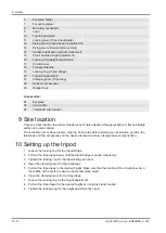
Page 15: ... 11 12 13 14 16 18 17 19 22 21 21 23 24 25 26 20 Illustration 1 Product images 7 Scope of delivery Optical tube assembly OTA A Tripod B 3 Eyepieces C Amici prism D Viewfinder E 8 Parts overview 1 Dew shield 2 Objective lens 3 Fixing screw Viewfinder bracket 4 Bracket Viewfinder 5 Eyepiece extension ...

Page 16: ...ts A flat and stable surface is recommended Do not observe from closed rooms Approx 30 minutes before starting an observation position the telescope and the accessories on the desired location to allow a temperature compensation 10 Setting up the tripod 1 Loosen the locking ring for the tripod bridge 2 Pull out the tripod legs slowly until the tripod bridge is opend completely 3 Tighten the lockin...

Page 17: ...e OTA Make sure that the fixing pin is reaching into the corresponding drill 4 Press the and hold the locking lever in position FREE and put the OTA with the attached tripod head plate into the holder Make sure that the objective lens is pointing to the opposite side of the handle 5 Press the locking lever to position LOCK 12 Installing accessories 1 2 3 4 5 7 8 9 6 Illustration 2 Achromat attachi...

Page 18: ...current horizontal position 3 Loosen the fixation for vertical movement by turning the handle counterclockwise Tilt the tripod head up and down 4 Turn the handle clockwise to to set the tripod head in current vertical position 5 Loosen the fixing screw for the tripod tilt plate to tilt the the attached optics sidewards for a viewing position up to 90 degrees 6 Tilt the tilt plate to the right and ...

Page 19: ...an eyepiece with a lower focal length 19 Troubleshooting Problem Error Possible solution No image Remove protection caps Use an eyepiece with lower magnification Blurred image Adjust the sharpness by turning the focussing wheel Focussing not possible Wait for temperature compensation Bad image Do not observe through glass panes Object visible in the viewfinder but not in the tele scope Adjust the ...

Page 20: ...s not a defect In this case let the device acclimatise for a short period of time at room temperature so that the residual moisture can dissipate After any residual moisture has been degraded put on the dust protection caps and store the tele scope in a closed box at a dry place that is free of mould It is recommended to store also the ac cessories in a closed container with desiccant bags dependi...

Page 21: ......

Page 22: ......

Page 23: ......

Page 24: ...e mail e mail sav bresser fr Téléphone 00 800 6343 7000 BRESSER France SARL Pôle d Activités de Nicopolis 260 rue des Romarins 83170 Brignoles France Prix d un appel local depuis la France ou Belgique Service NL BE Als u met betrekking tot het product vragen of eventuele klachten heeft kunt u contact opnemen met het service centrum bij voorkeur per e mail e mail info folux nl Teléfono 31 528 23 24...

Reviews: