46
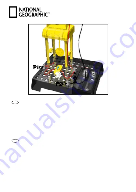
Fig. 9
F1
☛
F2
☛
F3
☛
O
1)
DE
Schritt 3 (Fig. 9)
Setze wie in Fig. 9 dargestellt den Widerstand (10) auf die
Grundplatte und verbinde die Kabel mit den Federanschlüssen wie
nachfolgend beschrieben:
Uhr, rotes Kabel: F3
Uhr, schwarzes Kabel: F2
Widerstand, rote Kabel: F1, F3
EN
Step 3 (Fig. 9)
Place the resistor (10) onto the base plate as shown in fig. 9 and
connect the cables with the spring connectors as described below:
Clock, red cable: F3
Clock, black cable: F2
Resistor, red cables: F1, F3


