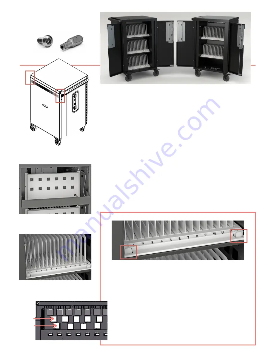
Changing the Slot Width from 1.25” to 1.5”
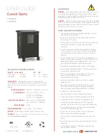
USER GUIDE |
CoreX CARTS
Device Storage & Cable Management
1.
At the back of the cart, unscrew the two security screws using the Security Bit provided.
Lift the back panel off of the chassis. This exposes the power outlet modules for each
of the three shelves.
2.
Starting in the rear of the cart with the back panel removed, insert a power adapter in
the storage bin for the associated device storage shelf (top, middle or bottom).
3.
Measure the amount of cable necessary to reach from the power adapter located in the
bin to the front of the cart (over the AC outlet box, from the back to the front of the cart,
through the cable management hooks). Leave sufficient slack for the power connector
to plug into the device.
4.
Plug the AC cord into one of the outlets nearest to where the power adapter is located
in the bin.
5.
Repeat the above process for the total number of devices’ power adapters & cable sets.
6.
In the front of the cart, insert a device into each of the slots, and plug in the power
connector to each device.
7.
Place the cart near a wall outlet and plug the cart in.
8.
Turn on the power switch - located in the front of the cord winder shroud
9.
Once the cart is turned on, the power manager begins rotating power to the 3 power
strips very 5 minutes. This allows efficient charing of the devices in the cart from one
single 15 amp circuit.
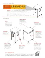
1. Unscrew the Security Screws - one on
each side of the cart at the back. Lift o
ff
the Back Panel.
1
TCOREX36
TCOREX24
Security Screws & Security Bit
1
rear view of the power outlet modules
2-5. Plug adapters in & thread power
connectors to the front of the cart
front view of the dividers & slot ID numbers
6. Hang the power connectors above the
slots using the slots hooks provided
1.
Slot widths ship automatically at the 1.25” width. If your devices need
the larger 1.5” width, follow these simple directions.
2.
Tabs located at the front of the plastic device platforms on each of the
shelves can be depressed, and the platform lifts out of the cart.
3.
Flip the device platform over, and remove each of the plastic dividers by
“pinching” the divider tabs that stick thru the platform.
4.
Reinsert the dividers into the square slots which create the 1.5” slot width.
(see the closeup at the left of the underside of the platform.)
5.
Flip the device platform upright and reinsert into the shelf.
6.
The slot number indicator can now be repositioned at “10”, replacing “12”
….. “20” replacing #24” and “30” replacing “36”
1.25”
1.50”
closeup underside of device platform


