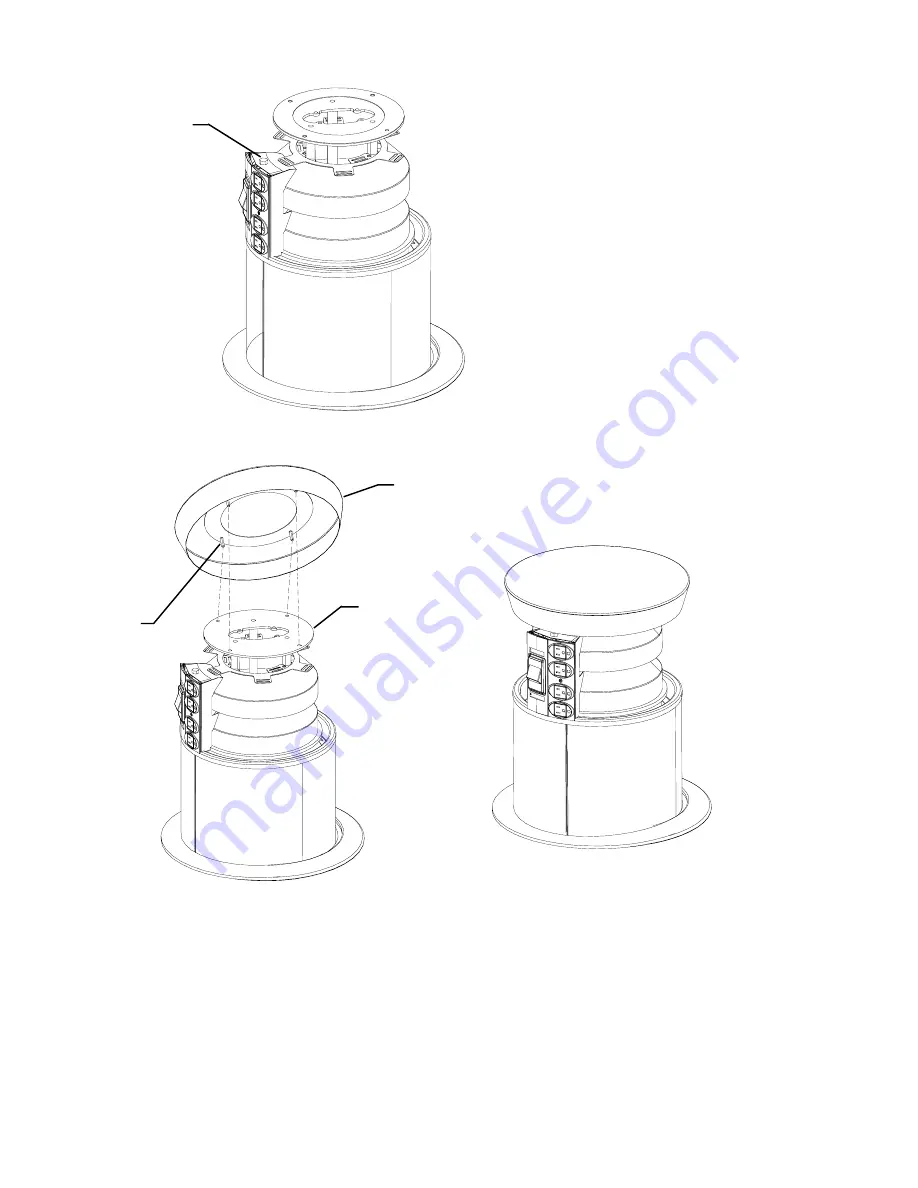
Fig. 5
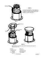
STEP 5
Lock the Power/Data Block in desired position by
turning the Locking Bolt Clock-wise. Reassemble
Visual Blocker, Substation Spider and Cover Pin
Plate (Fig. 5). Refer to steps 2 & 3.
Locking Bolt
Fig. 7
STEP 6
Replace Top Cover, while aligning the studs in the Top Cover with Cover Pin
Plate holes (Fig. 6 & 7).
Top Cover
Stud
Cover Pin
Plate
Fig. 6
Part #031-6469
Rev. 07.02.03 IM
Bretford
Bretford Ltd.
11000 Seymour Avenue
Technology House
Franklin Park, IL 60131
7 Lake End Court, Taplow
TEL: 847.678.2545
Bucks SL6 0JQ England
800.521.9614
TEL: 01628 603558
FAX: 847.678.0852
FAX: 01628 604923
800.343.1779
www.bretford.com


