Ceiling Mount Tray
Assembly Instructions
PARTS LIST
Qty
Part #
Description
1
010-4070
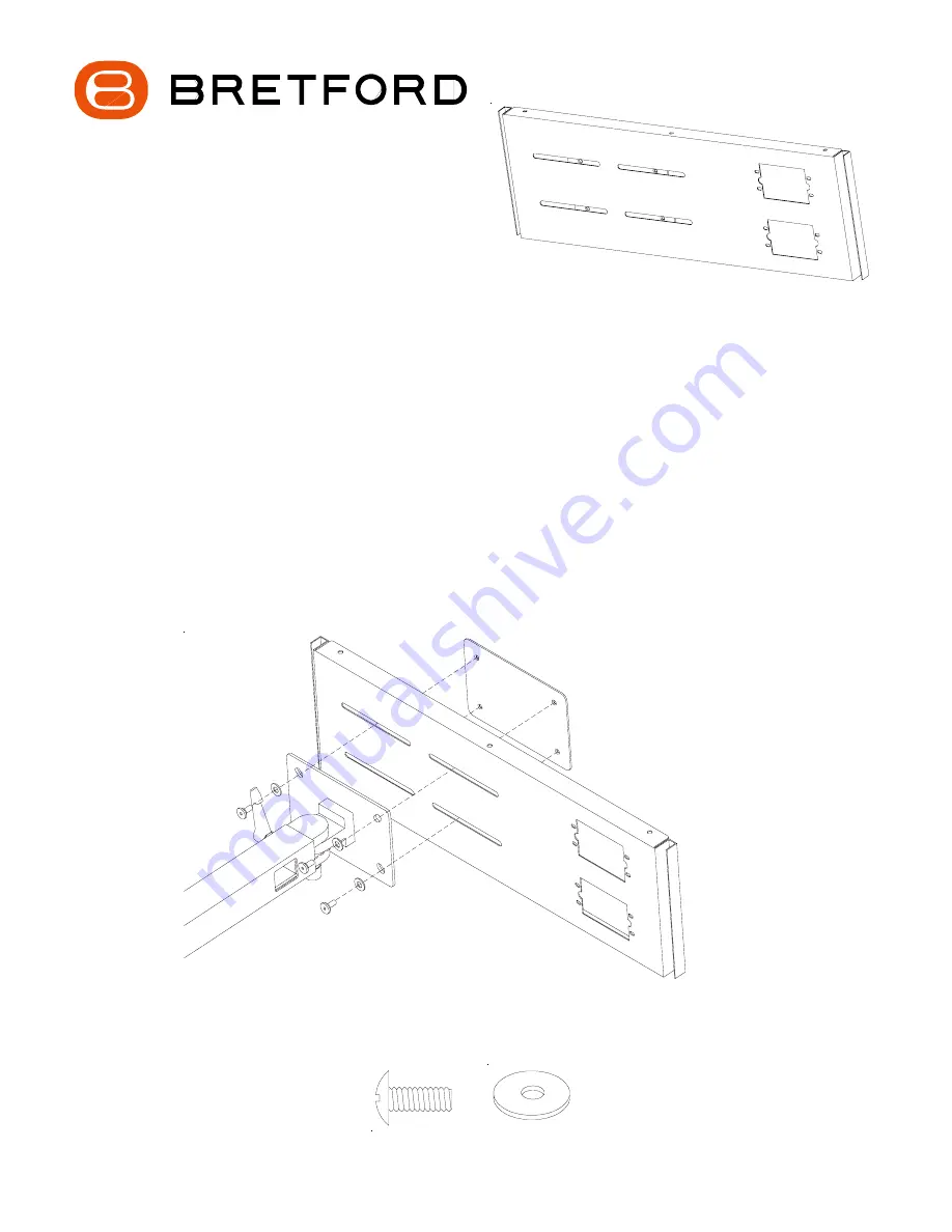
Ceiling Tray
1
010-4071
Back Plate
Ref.
Qty
Part #
Description
AA
4
030-0304
1/4-20 x 5/8" Truss Head Screws
BB
4
030-0305
7/8" x 17/64" x 1/16" Washers
CC
1
030-0989
10ft. 1/8 String Wire
DD
4
030-0985
1/4-20 x 5 1/2" Turnbuckles
EE
4
030-0986
Lag Screws
FF
4
030-0987
Concrete Anchors (1/4 x 1 3/4 tie wire)
GG
4
030-0984
10-24 x 5/8" Self Tapping Screws
HH
1
030-0990
12ga. Galv Soft 20' Safety Wire
II
2
030-0988
Safety Wire Clamps
HARDWARE LIST
WARNING
:
A QUALIFIED PROFESSIONAL SHOULD BE USED TO PROPERLY INSTALL
THIS UNIT TO THE CEILING. BRETFORD WILL NOT BE LIABLE FOR THE IMPROPER
USE OR INSTALLATION OF ITS PRODUCTS.
TPM8PLATE
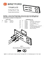
STEP 1
Attach the ceiling tray and back plate to your ceiling arm
mount as shown using screws (AA) and washers (BB).
NOTE:
YOUR PROJECTOR SHOULD NOT BE MOUNTED TO THE ARM MOUNT AT THIS TIME.
AA
BB


