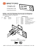
STEP 5
Insert screws (GG) into the sides of the ceiling tray as shown and tighten until the screws touch the track. Hook
the turnbuckles onto the four corners of the tray. Attach tie wire to ceiling anchors by pulling wire tight and twisting
it around itself at least four times. The weight of the ceiling tray should now be supported by the wire ties.
HOOK TURNBUCKLES INTO
THE (4) CORNER TRAY HOLES
SECURE THE SAFETY CABLE
Part # 031-6696
01.21.04 CH
Bretford
Bretford Ltd.
11000 Seymour Avenue
Technology House
Franklin Park, IL 60131
2 Etongate, 110 Windsor Road
TEL: 847.678.2545
Slough, Berkshire SL1 2JA England
800.521.9614
TEL: 01753 53 99 55
FAX: 847.678.0852
FAX: 01753 53 94 78
800.343.1779
www.bretford.com
WARNING: IT IS THE RESPONSIBILITY OF THE INSTALLER TO SELECT THE
CORRECT CEILING ANCHOR TO SUPPORT THE SAFETY CABLE AND THE
COMBINED LOAD OF ALL ATTACHED COMPONENTS.
1. Drill an anchor hole for the safety wire directly above the center of the ceiling tray.
2. Run the safety cable through the ceiling anchor. Pass each end of the wire through the holes in the ceiling tray
and join them with the cable clamp. DO NOT TIGHTEN YET.
3. Attach your projector to your arm mount.
4. Adjust the tension on the tie wires by adjusting the turnbuckles.
5. Take up the slack in the safety cable, leaving it slightly loose and tighten both safety cable clamps.
DO NOT TIGHTEN THE TURNBUCKLES NOW. FOLLOW INSTRUCTIONS BELOW.
WARNING: THE LOAD MUST BE CARRIED BY THE TIE WIRES,
NOT BY THE SUSPENDED CEILING TRACK.
GG
GG
CEILING
TRACK


