Fig. 2
STEP THREE
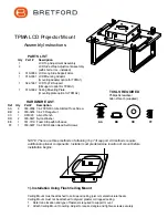
Secure Side Wrap Adjustment Assembly using 1/4-20 Truss Screws (AA) and Flange Nuts (BB).
NOTE: Screws installed from underneath. Repeat for second Side Wrap Adjustment Assembly.
STEP TWO
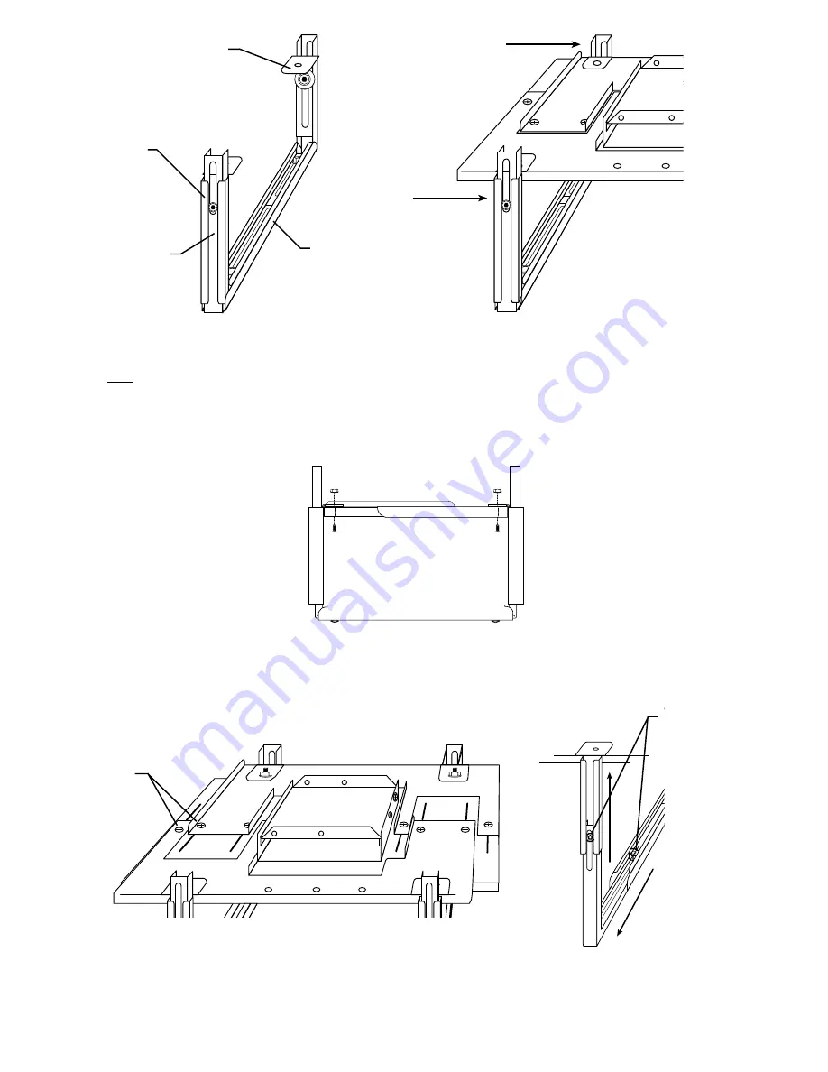
Have ready both Side Wrap Adjustment Assemblies (Fig. 1). Installer must determine whether to use long or short
Side Wrap Adjustment Assemblies according to height of projector being used. If projector is over 10 1/4" high,
use long side supports. If using long side supports, disassemble one Wrap Adjustment Assembly at a time, using
other as a reference, and replace short supports with long supports.
Note: Do not discard unused parts
.
Slide Side Wrap Adjustment Assembly onto Main Adjustable Plate Assembly (Fig. 2) and align with one set of
mounting holes. Choose position of Wrap Adjustment Assembly according to size and configuration of projector
and power cords.
STEP FOUR
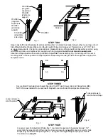
Loosen screws for Adjustment Plates (Fig. 1) and size the opening to be approximately 1 1/2"
wider than the largest width of the projector. Secure screws to a
snug fit
. Loosen screws for Side
Wraps (Fig. 2) and size the opening to be 1 1/2" higher than largest height of projector. Secure
the screws to a
snug fit
.
Fig. 1
Fig. 2
Fig. 1
Slide on
Loosen screws to
size the Side Wraps
AA
BB
Loosen screws to
size the plates
AA
BB
010-3086
(long side
support)
or
010-3087
(short side
support)
010-3088
(adjustable
side angle)
010-3089
010-3086
(long side
support)
or
010-3087
(short side
support)


