Part # 031-3120
Rev. 10.11.99 Holt
STEP FIVE
Note: Refer to your projectors owners manual to for image reversing operation.
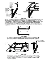
Turn mount upside down. Place projector in mount with top facing up and determine best locations for foam
strips (to be adhered at: top, bottom or sides. Note: top may require two layers of foam) to trap and stabilize
projector. Cut strips to 1" squares, remove protective backing and attach to mount (Fig. 1). Use at least four
foam pieces per Side Wrap Adjustment Assembly. With the projector in place, loosen screws to adjust width
and press together sides to secure the projector. Tighten screws while still pressing together. Loosen screws
on Side Wraps and press down on the assembly to secure the projector. Tighten the Side Wraps while still
pressing down. At this point, the projector should be FIRMLY in place. Readjust if necessary. When secure,
turn completed mount right side up (Fig. 2).
Fig. 1
Fig. 2
Ceiling Mount
Pipe Mount
STEP SIX
Insert 1/4-20 screws (AA) with plastic washers (DD) into threaded Center Tilt Support holes at "A", leaving 5/16"
space between Center Tilt Support and bottom of screw head. (Clearance to allow hardware to slip into "J" slot
of Top Tilt Support before tightening). Lift up and slide Mount Assembly into pre-mounted Top Tilt Support, being
careful to keep washers
inside
Top Tilt Support. Insert 2-1/4 - 20 screw with plastic washer between top tilt
support and center tilt support at "B". Do not tighten screws at this point.
STEP SEVEN
Adjust all tilts and swivel to achieve proper projection
image, then tighten all screws securely.
Center Tilt Support
Top Tilt Support
"A"
"B"
"A"
"B"
Bretford
Bretford Ltd.
11000 Seymour Avenue
Technology House
Franklin Park, IL 60131
7 Lake End Court, Taplow
TEL: 847.678.2545
Bucks SL6 0JQ England
800.521.9614
TEL: 01628 603558
FAX: 847.678.0852
FAX: 01628 604923
800.343.1779
www.bretford.com


