b250v
- 23 -
The soil can be broken up to various extents according to its na-
ture, the amount of moisture it contains, the ground speed, etc.
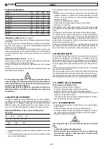
GEARBOX - 1000 rpm PTO (A= PTO)
A
B A
B A
B
21 - 16
19 - 18
18 - 19
286
230
207
* *
*
* One asterisk indicates the rotation speed with a tine rotor.
** Two asterisks indicate the rotation speed with the flash/spikes
rotor.
Proceed with these simple operations to change the speed of the
rotor:
- Unscrew the screws that fix the rear cover of the gearbox and
then remove the cover. Make sure that no oil spills out. This can
be prevented by slightly tilting the machine forwards.
- Remove the gears from the shafts.
- Insert the required pair of gears on to the shafts.
- Fit the cover back on.
Check the gears since gears from different pairs cannot be
mounted.
Only use the indicated gear pairs.
The higher the rotor rpm rate, the more the soil will be broken up,
but the power draw and tine wear will also be greater. It is always
advisable to use the lowest possible rotation speed able to till the
soil in the correct way.
The gearbox must only be adjusted or inspected with the ma-
chine unhitched from the tractor or with the tractor engine off and
the machine resting on the ground.
4.10 FRONT WHEELS
On request, the machine can be supplied with front wheels for
depth adjustment purposes. The adjustments are made by loos-
ening the screw (A Fig. 9) and lowering or raising the wheel. In
the former case, the depth becomes more shallow while in the
latter case it increases. Always remember to tighten the lock nut
sufficiently.
If the wheels are supplied separately, comply with the following
instructions to mount them on the machine:
- Mount the wheel support on the square section front tube and fix
it in place with the supplied U-bolts, taking care to tighten the
relative nuts to the correct extent.
When you remove the wheels, keep the side skids fully raised
since in this case, they only act as a protection.
4.11 STOPPING THE MACHINE
At the end of the job, the operator must:
- Disengage the tractor PTO.
- Lower the machine to the ground by means of the power lift.
- Stop the tractor and engage the parking brake.
- Make sure that all parts of the machine are at a standstill.
Only after the above mentioned operations have been carried out
may the operator leave the tractor unattended.
4.11.1 PARKING
- At the end of the job, the machine must be parked on a flat,
suitable surface.
- Stop the tractor and apply the parking brake.
- With the tractor stopped and all components at a complete stand-
still, remove the driveline from the PTO of the tractor.
- Unhitched the machine from the tractor.
WARNING
The place in which the machine is parked must be:
- Dry.
- Sheltered from adverse weather conditions.
- Guarded or locked up to prevent children or unauthorized
persons from freely accessing the machine.
CAUTION
If the machine is to remain idle for a long period of time, lu-
bricate the parts subject to wear and store the machine in a
dry, sheltered place, covered with a plastic sheet.
This will ensure that the machine is in the ideal condition
when required again.
SECTION 5
Maintenance
5.1 ROUTINE MAINTENANCE
The various routine maintenance operations are described be-
low. Remember that lower running costs and longer machine life
depend on continual compliance with these instructions.
WARNING
Before proceeding with any operation, make sure that the
machine is parked on a flat surface. Prevent it from moving
by placing chocks under the wheels.
Servicing, adjusting and the operations required to prepare
the machine for work must be carried out with the tractor
and the driveline detached from the machine.
The servicing frequencies indicated in this manual are in-
dicative and refer to normal conditions of use. They may there-
fore vary depending on the type of service, whether the envi-
ronment is dirty or not, seasonal factors, etc. The servicing
operations must obviously be carried out more frequently in
heavier duty service conditions.
CAUTION
- Before injecting lubricating grease into the grease nipples,
carefully clean these latter to prevent mud, dust or foreign
bodies from mixing with the grease as this would reduce
or even annul its lubricating effects.
Injection into the greasing points of a large quantity of
grease at high pressure can damage the bearing protec-
tion. This operation must therefore be carried out with the
greatest care.
- Lubricate and grease all the required points, including the
chains.
- Use oil of the recommended type for topping up and
changes.
Summary of Contents for B250V
Page 4: ... 4 b250v Fig 4 Fig 3 Fig 5 A B 1 3 MAX MIN 4 cm Fig 6 Fig 7 3 5 8 4 6 7 1 2 A ...
Page 5: ...b250v 5 Fig 9 Fig 8 1 2 3 4 5 Fig 10 A 6 7 1 2 3 4 A B Fig 7 a cm 40 ...
Page 61: ...b250v 61 Tav 6 0006615 5200451 0001020 0001177 5500367 ...
Page 68: ... 68 b250v Tav 13 ...
Page 69: ...b250v 69 Tav 14 0020675 E1200165 E1200165 8064873 0001020 0001019 8064565 0001042 ...
Page 70: ...b250v 70 Tav 15 Cod 8065842 ...
Page 71: ... 71 b250v Tav 16 Cod 8065846 ...

