background image

- 30 -

doble - maxi doble

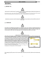
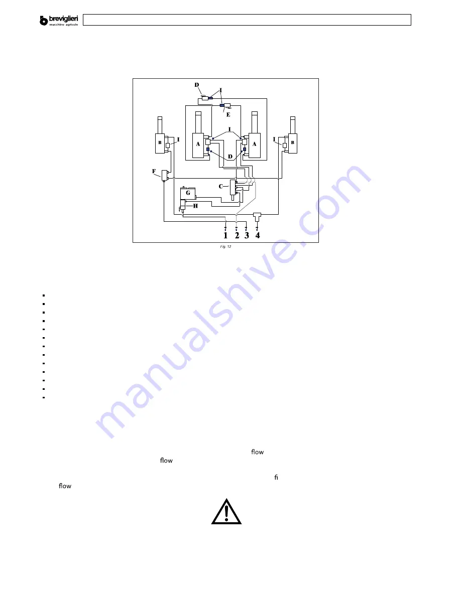
4.5 HYDRAULIC CIRCUIT


d

e

g

a

g

n

e


d

n

a

 r

o

t

c

a

r

e

h

f

o


s

t

n

i

o

p


e

e

r

h

e

h

o

d

e

h

c

ti

h

 .

e

.i

 ,

y

a

w

 t

c

e

r

r

o

c


e

h

n

s

n

o

it

a

r

e

p

o


y

r

a

n

i

m

il

e

r

p


e

h

t

u

o


d

e

ir

r

a

c


g

n

i

v

a

h

 r

e

t

f

A


e

h

w

o

ll

a


o

r

e

d

r

o


n

r

o

t

c

a

r

e

h

n

o


s

p

a

c

il

u

a

r

d

y

h


e

v

it

a

l

e

e

h

o

d

e

t

c

e

n

n

o

e

b

 t

s

u

m

 t

i

u

c

ri

c


c

il

u

a

r

d

y

h


e

h

f

o


s

e

p

i

p


e

h

,

e

n

il

e

v

ir

d


e

h

t

various components of the implement to operate.

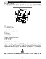
KEY Fig.12

MAXIMUM PRESSURE 180 Bar

1/4” AND 3/8” HYDRAULIC PIPES

A) Hydraulic cylinders to control steerage hoe


B) Hydraulic cylinders to regulate rollers


C) Hydraulic cylinder to hitch/unhitch steerage hoe


D) Control cylinder speed adjuster valve


E) Floating valve


F) Flow divider


G) Sequence valve


H) Safety valve


I ) Locking valve


1) Harrow closing/harrow hitching oil pipe


2) Harrow opening/harrow unhitching oil pipe


3) Roller lowering oil pipe


4) Roller lifting pipe


4.6 HOEING UNIT OPENING/CLOSING

The two hoeing units are respectively opened during the work phase and closed when the machine is transported on the roads 

by  a hydraulic control with two cylinders (16 Fig. 1 and 4 Fig. 8). Both hydraulic cylinders are equipped with locking valves (17 Fig. 
1). If a hydraulic pipe suddenly bursts, these valves instantly stop the oil 

 and, consequently, the machine in the position to 

which it has set. The cylinders also have a 

 valve that regulates the opening and closing speeds of the hoeing units (D Fig. 12). 

These  valves are calibrated so that the movement of the cylinders and, thus, the lowering and lifting movements of the hoeing 

  t

u

n

 r

e

n

i

a

t

e

e

h

g

n

i

n

e

s

o

o

r

o


g

n

i

n

e

t

h

g

it


y

b


d

e

i

d

o

m


e

b


n

a

c

 t

n

e

m

e

v

o

m

 s

i

h

T

 .

e

l

b

i

s

s

o

p


s

a


s

u

o

e

n

e

g

o

m

o

h


d

n

a


h

t

o

o

m

s

 s

a


e

r

a

 ,

s

ti

n

u

of the 

 governor valve until the two side hoeing units lift and lower in the desired way. After this, lock the valve in position 

with the ring nut in the governor valve.

WARNING

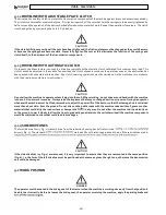
When the hoeing units are in the vertical position, check the rear visibility from the driving seat in the tractor as it could be 

obstructed with the hoeing units in this condition. In this case, you are advised to mount one or more rear view mirrors on 

the tractor in order to ensure unobstructed visibility.

Summary of Contents for DOBLE

Page 1: ...con la máquina leer atentamente las instrucciones para el empleo Mantenga esto manual como referencia futura Betriebs und Wartungsanleitung Originalbetriebsanleitung Bevor Sie mit der Arbeit beginnen lesen Sie diese Betriebsanleitungen aufmerksam durch Bewahren Sie dieses Handbuch zum Nachschlagen e s e i D e i r é s e d o r é m u n u d r i t r a p à e l b a l a v t s e l e u n a m e C r e b m u n...

Page 2: ...ay not exactly depict the machine in your possession they are included for the sole purpose of explaining the operations that must be carried out 1 2 WARRANTY The Manufacturer guarantees brand new products for a period of 12 twelve months from the date of delivery When the machine is delivered make sure that both it and the accessories are complete and in a perfect condition Complaints should be p...

Page 3: ...Free 1 3 DESCRIPTION OF THE MACHINE doble and maxi doble rotary tiller bears CE marking in compliance with the European Union standards described in directive 2006 42 EC Fig 1 Central bearing frame with three point hitch Upper 3 point hitch Connection point to lift the machine Lower 3 point hitch Main driveline support Central transmission unit PTO to engage main driveline Lh upper steerage hoe fr...

Page 4: ...or of adequate power see technical for the power rating required To operate the machine drive is transmitted from the tractor by means of the driveline with CE marking which meshes with the central transmission unit 7 Fig 1 and is distributed between the two side transmissions 11 Fig 1 which operate the respective hoe blade rotors by means of a side geared transmission unit 1 3 2 USE has solely be...

Page 5: ...ons 2 1 SAFETY NOTES The user must inform his the risks deriving from the devices to safeguard the operatorand outthe gen accident preventing tions est shed theDirectives and the sinforceinthecountr where the machine is used It is therefore for operators to read this the and The to with the in lbs CV kW knives doble 360 142 4564 5225 5688 150 220 110 162 84 doble 400 157 4806 5600 6173 180 220 132...

Page 6: ... lower it to the ground and consult the instruction manual Hitching points to lift the machine Carefully read the instruction manual before beginning work Danger of upper limbs Do not remove the guards and keep well away from moving parts Danger of being caught up by the driveline It is absolutely forbidden to get near the driveline when it is operating Danger of falling It is absolutely forbidden...

Page 7: ... tractor and the machine hitch in order to manoeuvre the lifting command from the outside Fix the side lifting links with the relative chains and idlers during the transport phase Set the control lever of the tractor s hydraulic lifting control in the locked position when driving on the roads with the ma chine raised Only use the driveline recommended by the Manufacturer with CE marking Pay the ut...

Page 8: ...ine Loading with a crane make sure that the carrying capacity of the crane is to lift the weight of the machine The connecting points for lifting are clearly visible and are marked by stickers Lift the machine with the utmost care and move it slowly without jolting on to the truck or railway car DANGER The lifting and transporting operations can be very dangerous unless they are carried out with t...

Page 9: ...work with the utmost care so as to keep the telescopic tubes coupled to the maximum extent With the exception of length adaptation it is forbiddento modify the driveline If this is necessary contact the Manufacturer Take the greatestcarewheninsertingthedriveline Make surethatit iswelllockedon both the tractor s PTO and on the machine Also comply with the indications in the instruction manual suppl...

Page 10: ...ine to operate unless it digs into the soil When working do not drive around bends with the machine in the soil Do not work in reverse Always raise the implement before you change direction or reverse During transport or whenever the machine must be lifted remember to adjust the power lift of the tractor so that the steerage hoe is not raised more than about 16 in from the ground Do not drive on t...

Page 11: ...llowing way to hitch the machine to the tractor in the correct way Make sure that there are no objects bystanders and or animals in the immediate vicinity of the machine and that the PTO 6 1 4 4 TRANSPORT POSITION 5 M x s 0 2T x i Z d i M 0 3T Z M x s 0 2T x i d x i where i tractor s wheelbase d s T weight of the tractor in running order Z ballast weight M weight of the machine Fig 5 ...

Page 12: ...ned during the work phase and closed when the machine is transported on the roads by a hydraulic control with two cylinders 16 Fig 1 and 4 Fig 8 Both hydraulic cylinders are equipped with locking valves 17 Fig 1 If a hydraulic pipe suddenly bursts these valves instantly stop the oil and consequently the machine in the position to which it has set The cylinders also have a valve that regulates the ...

Page 13: ...y after you have correctly hitched the machine sat down in the driver s seat of the tractor and started the tractor engine Raise the machine about 10 cm from the ground so that the rotor does not touch the vegetation that needs to be cut Run the engine at a low rate and engage the PTO Gradually accelerate until the PTO is operating at full rate Engage the forward gear and start work with the PTO a...

Page 14: ...from foreign bodies in the central part Other faults The machine fails to work evenly along its width shredding either too much or too little on one side for example on the right shorten the right link Work on hilly ground It is advisable to proceed upwards in the direction of the slope Particular attention should be paid since owing to the nature of the ground the stability of the tractor could b...

Page 15: ...is version is with a special spiked rotor on highly resistant pressed steel Can be equipped with levelling seed beds on tenacious and stony soi DANGER It is forbidden to clean the machine whilst it is if the hoe blades knives become First the PTO the tractor and the Wait until all have come to a standstill then 4 9 STOPPING THE MACHINE At the end of the job the operator must Disengage the tractor ...

Page 16: ...tof the national laws Maintenance 5 1 ROUTINE MAINTENANCE The various routine maintenance operations are described below Remember that lower running costs and long machine life depend on continual compliance with these instructions WARNING Before proceeding with any operation make sure that the machine is parked on a surface Prevent it from moving by placing chocks under the wheels Servicing adjus...

Page 17: ...ricated more frequently DANGER Greasing the central rotor supports is a dangerous operation Proceed in the following way to grease the central rotor supports of the two cultivators 5 2 1 RECOMMENDED LUBRICANTS It is advisable to lubricate the overdrive with PAKELO GEARSINT EPN46 oil complying with DIN 51517 Part 3 CLP HC US Steel 224 AGMA 9005 E02 ISO 12925 1 CKC CKD For all greasing points the Ma...

Page 18: ...e required part indicated in the spare parts catalogue a description of the part and the required quantity The means of transport Transport way if this is not the Manufacturer willdedicate particular care to the service but shall not be liable for delays in shipment due to unforeseen circumstances The shipping costs are always at the consignee s charge The goods travel at the purchaser s risk and ...

Page 19: ...doble maxi doble 37 ...

Page 20: ...âssis 96 Pl 6 Transmission latérale à engranages 97 Pl 7 Kit Ancre e ace trace 98 Pl 8 Convoyeur disc 99 Pl 9 Rotor 100 Pl 10 Châssis Rouleau 101 Pl 12 Rouleau à cage 103 Pl 13 Rouleau Packer 104 Pl 14 Circuit hydraulique pour rouleau 105 Pl 15 Capot 106 Pl 16 Capot 107 DEUTSCH ERSATZTEILTAFELN Taf 1 Gerät 92 93 Taf 3 94 Taf 4 95 Taf 5 Gestel 96 Taf 6 97 Taf 7 Anker kit für Spurbrecher 98 Taf 8 Le...

Page 21: ...doble maxi doble 92 Tav 1 ...

Page 22: ...doble maxi doble 93 ...

Page 23: ...020 0001018 0073012 0030358 Z0200117 DX RH v DUO CONE Z0200118 SX LH v DUO CONE Z0100283 DX RH v 360 400 460 500 560 ACQUA Z0100277 SX LH v 360 400 460 500 560 ACQUA Z0200115 DX RH v 630 DUO CONE Z0200114 SX LH v 630 DUO CONE 8065132 0001067 8065111 Z0200030 8065118 0021105 0070582 Z0100041 0007224 0056807 ...

Page 24: ...doble maxi doble 95 ...

Page 25: ...doble maxi doble 96 ...

Page 26: ...doble maxi doble 97 Tav 6 ...

Page 27: ...doble maxi doble 98 ...

Page 28: ... v 560 Z0150298 v 500 Z0146298 v 460 Z0140298 v 400 Z0136298 v 360 5501616 0077535 0077535 8064948 8064948 8064948 0077536 8065791 8065791 Z0200023 0060356 0060356 0032949 0031182 8064948 8064948 0032949 5500493 8064436 0002265 0003038 0073404 0073404 ...

Page 29: ...doble maxi doble 100 ...

Page 30: ...doble maxi doble 101 ...

Page 31: ...doble maxi doble 102 ...

Page 32: ...doble maxi doble 103 ...

Page 33: ...doble maxi doble 104 ...

Page 34: ...doble maxi doble 105 ...

Page 35: ...doble maxi doble 106 ...

Page 36: ...doble maxi doble 107 ...

Page 37: ...Via Labriola 2 37054 NOGARA Verona ITALY Tel 0442537411 r a Fax 0442 537 444 Export Tel 0442 537 402 www breviglieri com info breviglieri com export breviglieri com ...

Reviews: