47
MekFarmer 170
CAUTION
Check proper tightening of fittings and hydraulic tubes.
5.6.5 INSTALLING HYDRAULIC SEEDER
LINKAGE (OPT)
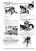
FIG. 28
•
Once the frame is fitted on the machine, make sure that
to lift the seeder with the seeds, the overall weight of
the combine does not exceed the one indicated in the
instruction and maintenance manual of the tractor.
•
Make sure that the coupling, and the working of the see
-
der when lifted, is correct and that there is no inference
with the hydraulic tubes.
•
Make sure that the mechanical parts of the seeder do
not interfere with the machine roller or with the machine
itself.
•
When transporting the machine on public roads, make
sure that no blunt object sticks out from the contour of
the machine.
•
Make sure that the visual signals at the rear of the com
-
bine machine can be seen properly or otherwise proce
-
ed as required by the Highway code of the country where
the machine is being used.
CAUTION
During transport on public roads the seeder hopper
must always be emptied of any product.
5.6.6 SEED DRILL HYDRAULIC CONNECTION
(OPT)
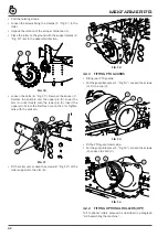
After installing the linkage to the machine, to check pro
-
per operating of the lift, connect the linkage hydraulic
tube to the tractor PTO and put pressure so as to allow the
activation of the structure on the machine. Carry out this
operation load-less two or three times making sure that
everything works properly and that there is no mechanical
or hydraulic hindrances. Before carrying out these opera
-
tions, make sure there is no-one near the machine. The
descent of the seeder linkage is spontaneous when there
is no pressure in the system as the cylinder is at single ef
-
fect. It is equipped with a check valve in case of a sudden
breakage of the tubes.
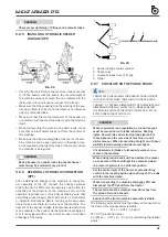
2
1
1
3
4
FIG. 29
1 Seeder linkage control cylinder.
2 Check valve.
3 Hydraulic tubes from 3/8” gas.
4 Gaiter.
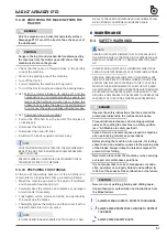
5.6.7 CIRCULATE ON THE PUBLIC ROADS
NOTE
COMPLY WITH THE HIGHWAY CODE REGULATIONS IN FORCE
IN YOUR COUNTRY WHEN TRAVELLING ON PUBLIC ROADS.
CONSULT “2.7 OVERALL DIMENSIONS” FOR THE WEIGHT AND
DIMENSIONS. THIS WILL ALLOW YOU TO MAKE SURE THAT
THE MACHINE CAN PASS THROUGH TUNNELS OR LOW CON
-
STRUCTIONS WITHOUT DIFFICULTY.
CAUTION
When required by road regulations, on-road transport
must be carried out with reflex reflectors, flashing
lights, slow vehicle and protruding load signals. Put
these signals on the rear side of machine in a well
visible manner. When transporting at night or with poor
visibility install warning and side marker lights.
It is absolutely forbidden to transport persons or ani
-
mals on the machine.
When driving round bends with and without the machi
-
ne, take care of the centrifugal force exercised when
the center of gravity is in a different position.
Set the control lever of the tractor’s hydraulic lifting
control in the locked position when driving on the roads
with the machine raised.
When transporting the machine disengage PTO and
disconnect the PTO shaft from the tractor.
The machine must be raised at least 16 inches from
the ground for road transport.
Ensure that the tractor-machine assembly is stable.
The following expressions must be observed to ensure that
the tractor-machine assembly is stable:
M x s ≤ 0,2T x i + Zx(d+i)
M
≤ 0,3T (prudential value)
Z ≥ {[(M x s) – (0,2T x i)] / (d + i)} (for calculating the ballast)
where:


