40
Treadwall M6 Pro Owner’s Manual—2017
Main Channel Assembly
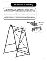
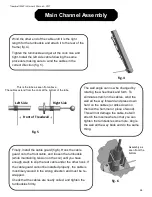
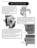
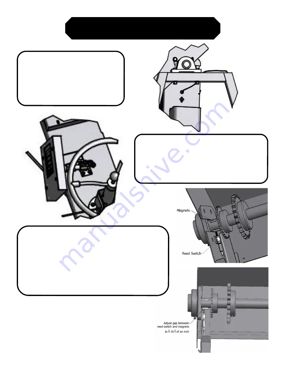
Bring the wire from the top of the right
A-frame through the grommet near the
top of the right channel and down
through the wire clips. Inside, about a
foot below the grommet, plug it into the
main wiring harness.
Mount the counter-timer on the right channel to
the four small holes below the speed control - with
the provided screws and nuts. The sensor wire
and power wire are pre installed and plug directly
into the rear of the counter.
There are three magnets packed with the right channel
that must be placed on the upper shaft, just to the right
of the small sprocket. Place them flat side down and
they will stay on by magnetic attraction.
The sensor which is mounted just below the shaft on the
inside of the channel should be adjusted so that the
magnets pass about 1/8" above the sensor.
Summary of Contents for Treadwall M6 Pro
Page 2: ......
Page 4: ...ii Treadwall M6 Pro Owner s Manual 2017...
Page 6: ...2 Treadwall M6 Pro Owner s Manual 2017...
Page 8: ...4 Treadwall M6 Pro Owner s Manual 2017...
Page 14: ...10 Treadwall M6 Pro Owner s Manual 2017...
Page 16: ...12 Treadwall M6 Pro Owner s Manual 2017...
Page 50: ...46 Treadwall M6 Pro Owner s Manual 2017...

