background image

 46 

Treadwall®FT Owner’s Manual—2019 

Rev Aug 2019 

Operating Instructions 

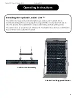
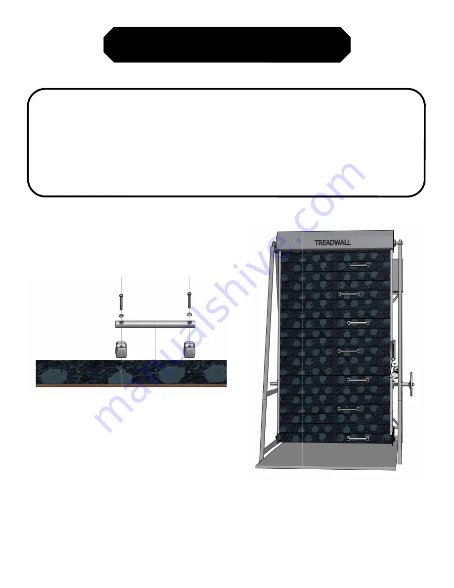
Installing the optional Ladder Line™ 

The Ladder Line rungs can be installed anywhere you wish on your Treadwall, but we 
recommend starting with an even spacing of the rungs with little or no deviation from side to 
side. This provides the best platform for simple aerobic training and fast sprinting climbs.  

The Ladder Line is an excellent way to introduce the Treadwall to those who have not climbed in 
the past or feel nervous about the Treadwall. 

Ladder Line Staggered Pattern 

Ladder Line Assembly 

Summary of Contents for TREADWALL Max Frame

Page 1: ...TreadwallFT Series Owner s Manual Max and S Frames 87 York Ave Randolph MA 02368 USA 781 961 5200 www brewerfitness com Copyright 2019 Brewer Fitness Rev August 2019...

Page 2: ......

Page 3: ...d setup Making Your Treadwall a Success Information for Your Staff Training Tips Guidelines Activities Promotional Ideas Frequently Asked Questions General Maintenance Troubleshooting Service Instruct...

Page 4: ...itness tool The owner s manual is designed to help managers staff and trainers take full advantage of this equipment This reference tool emphasizes the benefits of vertical movement with links and res...

Page 5: ...rpose Specifications Max Frames S Frames V Frames Weight Width climbing surface 4 feet 6 feet 4 feet 6 feet 4 feet 6 feet Length climbing surface 18 20 22 feet 18 20 22 feet 18 20 feet hold Placements...

Page 6: ...weight of your body will move the wall downwards With our auto stop technology if you stop climbing the Treadwall will stop and wait for you when your feet reach the bottom The Treadwall will not mov...

Page 7: ...min or meters min as required Option 1 Option 2 Changing the Angle The angle of the wall makes a big difference The Treadwall can be adjusted Max and S Frames over a range of angles from a relatively...

Page 8: ...2 3 4 5 6 7 8 9 0 Clear Home Screen The home screen shows real time data for a single climb When you pause for 5 seconds the counter will hold your data on the screen until you begin climbing again a...

Page 9: ...ost We recommend that a staff person be chosen as the main advocate for the product s introduction period This person might take on the following responsibilities 1 Read through the manual thoroughly...

Page 10: ...or as part of a circuit routine with oth er equipment Customize it to suit YOUR needs and GOALS 1 You should use the equipment yourself Get a first hand look at how the workout makes you feel learning...

Page 11: ...s on smooth movement 5 Emphasize the need to move your feet above a certain panel to keep the wall moving Auto stop will automatically stop the rotation as they approach the bottom 6 Tell them they ca...

Page 12: ...s on the benefits of climbing etc 2 Refer to our website for full training program ideas and short workouts Climbing is a progressive activity there is a great deal to learn about balance and techniqu...

Page 13: ...imbing 1000 feet a day seven days a week it will take a full month For most people it will take the bet ter part of a year Anybody who completes this challenge will come out a different person fitter...

Page 14: ...5117 Devil s Tower Wyoming 5267 Mt Katahdin Maine 6288 Mt Washington New Hampshire 7310 Mt Koscivsko high point in Australia 7569 El Capitan Yosemite National Park 8842 Half Dome Yosemite National Par...

Page 15: ...ttern get repetitious Eventually but it takes much longer that you might expect The Treadwall has no beginning or end and it con nually presents you with new challenges and possibili es It is simple t...

Page 16: ...imbing play equipment and trees For adults climbing on the Treadwall recaptures much of that simple joy and natural vertical movement What kind of bodies does Vertical Movement build Climbing and gymn...

Page 17: ...chain Our auto stop system is triggered when the weight of the climber s foot reaches the bottom panel The Treadwall will not move when someone is standing and not climbing upwards The internal senso...

Page 18: ...o access the inside of your Treadwall The Treadwall wall panels are bolted to a set of chains These two chains form a continuous loop around the top and bottom axles Each panel is attached to flanges...

Page 19: ...needs adjust ment Check and adjust the small switch at the bottom of the right channel Also make sure that unit is plugged in and receiving adequate power Wall is sluggish lighter weights will not pul...

Page 20: ...adjustment If the internal X bracing is too tight the panels may be restricted in their movement If too loose the wall can sway from side to side For best function the center section of the Treadwall...

Page 21: ...it with your finger at the inspection hole There should be no slack but not too tight CAM PULLEY CABLE ADJUSTER Speed Lever Adjustment 1 Adjust the speed lever to the slowest position 2 The hydraulic...

Page 22: ...h needs to be inspected further or replaced remove the plastic access hole cover and all nuts and washers from the microswitch Reach inside of the access cover and unclip the electrical wire from insi...

Page 23: ...wo in the back Each channel has a rear surface and a front surface 3 To lubricate the rear surfaces first put newspapers or a rag under the channels to catch drips 4 Put the nozzle into the gap betwee...

Page 24: ...m of the left channel black plastic cover two phillips head screws The caliper is located just below the access hole and is easily reached through the access hole The caliper has a knurled knob about...

Page 25: ...but the display and auto stop will not work Fromright side frame top or bottom depending on unit the power wire enters the right channel where it is connected to the interior wiring during assembly F...

Page 26: ...the Treadwall Spatial Requirements Make sure there is at least a meter of clear space behind the Treadwall for assembly Once the wall is upright you can move it into position if needed References to r...

Page 27: ...tools that are not typically found in a tool kit All the other tools are common Assembly will take 6 10 hours please read the entire assembly procedure prior to installing If you have questions conta...

Page 28: ...40 Align frame and channels to match swing of angle cassettes p 40 Panel Stiffeners p 41 Attach first 1 or 2 panels p 41 Testing p 42 Auto stop Counter Alignment interior x bracing Alignment exterior...

Page 29: ...ames Max shown 2 Horizontals Max 3 horizontals S 2 horizontals 3 X Bracing there are 2 or 4 exterior X braces S frame 2 Max frame 4 exterior x braces Turnbuckles are in the hardware box 4 Hardware bag...

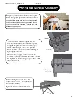
Page 30: ...the wire when assembling the horizontal bolts The turnbuckles attach between the long and short X braces short X braces at bottom Before attaching the turnbuckles turn them out so that they are close...

Page 31: ...at the bo om The turnbuckles go on the lower ends Note the alignment strip at the front between the front feet Alignment strap Third horizontal and lower x bracing with shorter extension piece S frame...

Page 32: ...size 3 Top and bottom shafts 4 Right with hydraulic box and left channels 5 4 chain boxes 6 Top Shroud 7 Back Guard 8 Spacer bar 9 Side covers 4 black plastic 10 Hardware Box 11 Pro Package Holds Lad...

Page 33: ...speed lever It is good to pad the top horizontal The channels have a shaft hole through which the end of the bearing shaft goes this helps when mounting Note the right channel will swing back due to t...

Page 34: ...the top shaft The shaft has a right and left side the right side has TWO sprockets Install the first three nuts per diagram Bag FT 30 leave as loose as possible so that the shroud can be slipped unde...

Page 35: ...d insert 4 bolt Then pivot the shroud up and when firmly pushed forward all the way tighten bolts 1 and 2 As step tighten bolt 3 4 Slide the shroud under the bearing and Insert the last bolt 4 in both...

Page 36: ...on the outside of the channel The black plate has a slot in one side slide the slot end in first then rotate the shaft so the slots face to the front top at this point There are three bolts Bag FT 50...

Page 37: ...ace the brake caliper over the brake disk This is done when the brake disk is moved 5 6 10 12cm away from the channel When the caliper is mounted on the disk slide both togeth er and mount it on the t...

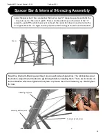
Page 38: ...tightened firmly later to prevent them from loosening up Hand tighten for now Turnbuckles at bo om X Bracing top point X Bracing bo om point Install the spacer bar This is a plain bar that rest on two...

Page 39: ...go There are three paired magnets and one sensor in the hardware box The three paired magnets are placed evenly around the upper shaft just to the right of the small sprocket Place them flat side dow...

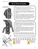
Page 40: ...make it too tight Too much tension will make the Treadwall run sluggishly Tighten locking nut Pushdown Bolt To disassemble the master links use a pair of pliers or a flat blade screw driver to press a...

Page 41: ...e wall back towards vertical By twisting the channels and slipping the ends of the bottom shaft into one side then the other the bottom shaft can be placed inside the frame to its final location This...

Page 42: ...ley bracket Replace the pulley over the cable Attach a spring and turnbuckle to the end of the back cable and hook the turnbuckle on the turnbuckle hook Rewind the front cable on the correct side With...

Page 43: ...tom sprocket and while lifting up the bottom shaft attach the front half of the chain Repeat on the other side Note the sprocket on the left side has no set screw and you have to move it to line up wi...

Page 44: ...f the chains are different as shown below Attach the end of chain A with a single extra link to the end of chain B that has five links This will insure that the spacing between the chain tabs is corre...

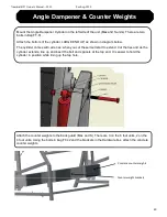
Page 45: ...th wire ties when you cut these it will start to extend Cut the ties and as the cylinder extends line up and insert the bolt and spacers at the top end It is easier to hold the cylinder in position wh...

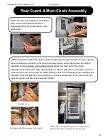
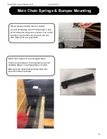
Page 46: ...d S hooks these in bag FT 40 Attach on each side as shown The cord in the bag is used to lift hook into place over the TOP edge of the rear guard side Mount the bumpers on the rear guard sides There a...

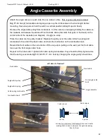
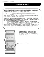
Page 47: ...ged the two angle cassettes have to move exactly inside the frames This may require 2 3 adjustments to get correct This is important The basic adjustment is the same for all machines when you are faci...

Page 48: ...a 2 Philips bit and a socket wrench with a 3 8 socket Do not overtighten the screws If your drill has a clutch use a low setting so that the head of the screw seats down but does not dig into the pan...

Page 49: ...er Plug in the transformer and do the following tests Make sure display turns on few seconds are required Touch the screen if needed to activate Slide speed lever to fast push in auto stop actuator at...

Page 50: ...is because there are more panels at the back of the wall heavier than the panels in the front When this happens insert blocks of 2x4 wood between the bottom panels as shown below to jam the wall and p...

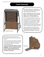
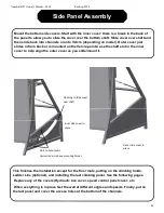
Page 51: ...t panel and cover the access holes at the bottom of the channels Mount the bottom side covers Start with the inner cover there is a break in the back of the panel to allow you to slide the cover over...

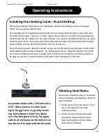
Page 52: ...but we recommend starting with an even spacing of the rungs with little or no deviation from side to side This provides the best platform for simple aerobic training and fast sprinting climbs The Ladd...

Page 53: ...to create a route around the wall using just green holds place holds approximately every 2 3 panels Try climbing when done adjust as needed If you find any move too difficult just move a nearby hold...

Page 54: ...continue down and stop moving downward when your foot reaches the bottom of the wall and triggers the micro switch at the bottom of the right channel Do this test at all the angles The micro switch is...

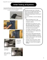
Page 55: ...ok for loose holds make sure the auto stop is working and the when changing wall angles the bottom covers are not pushed Angle cassettes are aligned Mount the last panel re mount the hydraulic box cov...

Page 56: ...Original Purchaser and Brewer s Ledge Inc or their authorized dealer 5 WHAT IS NOT COVERED Normal wear and tear are excluded from this warranty Damages caused by a lack of maintenance outlined in the...

Page 57: ...ipment the cost of capital the cost of subs tute equipment facili es or services down me the claims of third par es including customers and injury to property This limita on does not apply to claims f...

Page 58: ...9 Rev Aug 2019 Contact Information Website WWW BREWERFITNESS COM Email SALES BREWERFITNESS COM Address Please contact us anytime to come by for a visit 87 York Avenue Randolph MA 02368 USA Phone 1 781...

Reviews: