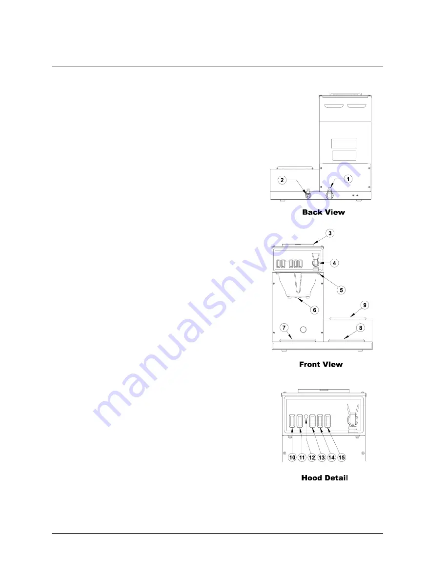
Control Locations And Descriptions
Fig. 1.
1.
Water Inlet Fitting.
The incoming water supply connects here.
2.
Power Supply Cord.
Connect this cord to an appropriate wall receptacle.
3. Pour-In
Opening.
(Except CCP models 1034525 & 1034526)
Pour water in here during installation to fill the water tank.
4.
Hot Water Faucet.
Open to get hot water for tea, hot chocolate, etc..
5.
Brew Cone Rails.
Slide the brew cone in here.
6. Brew
Cone.
Place the paper filter and ground coffee in here.
7. Left
Warmer.
Place a decanter of coffee here to keep it hot.
8. Right
Warmer.
Place a decanter of coffee here to keep it hot.
9. Top
Warmer.
Place a decanter of coffee here to keep it hot.
10. Power
Switch.
Turns on the power to the coffee brewer.
11. Start
Switch.
Press to start a brew cycle.
12. Ready
Light.
Indicates that the coffee brewer is ready to brew coffee.
13. Left Warmer Switch.
Turns on the power to the left warmer.
14. Right Warmer Switch.
Turns on the power to the right warmer.
15. Top Warmer Switch.
Turns on the power to the top warmer.
Note:
1034505, left hand model is shown in all illustrations.
Installation and operation is similar for all models.
Page 4
COMK211


