Bridge BRDSC01 v4
User Manual
8
•
TLS version: 1.2
•
Current Consumption (typical): 115mA average, 500mA peak
•
Operating Temperature: 0ºC-40ºC(32°F-104°F)
Installation instructions (Wiring)
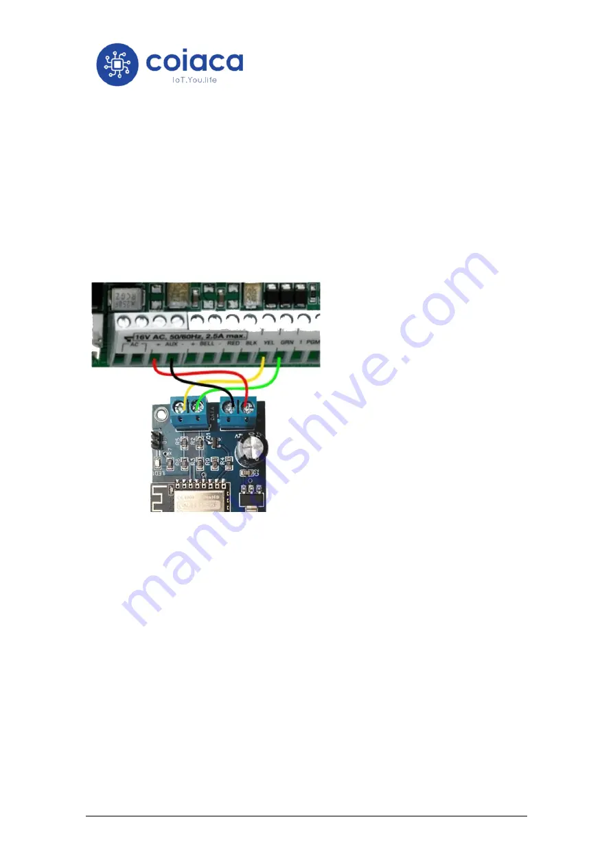
Connecting the bridge to the alarm system y very simple. Using four wires make the following
connections:
•
The
CLK
terminal on the bridge to the
YEL
terminal on the alarm panel.
•
The
DATA
terminal on the bridge to the
GRN
terminal on the alarm panel.
•
The
+
terminal on the bridge to the
AUX+
terminal on the alarm panel.
•
The
-
terminal on the bridge to the
AUX-
terminal on the alarm panel.
Probably, the terminals on the panel are
already in use. Don´t disconnect the
connected wires, just add the new ones
from the bridge to the terminals.
Because of the low voltage on the terminals, there is no risk of electric shock but while
touching the wires, the alarm system could be triggered due the anti-vandalism mechanism. If
this happen just disarm the system by entering the code on any keyboard.
If your alarm system is being monitored, be prepared to receive a contact from your
monitoring service provider, in case alarm system is triggered. Other option is to put the
monitoring service provider in aware of the installation beforehand, to make him dismiss the
event.
Connecting Accessories
12v can be supplied from the alarm system through the device and digital Pins 1 and 2 can be
used to connect external accessories to be controlled by de device.
The way the pins are controlled depends on the firmware version. Please refer to the online
documentation on coiaca.com to get the reference accordingly.


