Copyright © Bridgetek Pte Ltd
13
PanLHub44/80 Datasheet
Version 1.0
Document Reference No.: BRT_000277 Clearance No.: BRT#146
6
Setup Instruction
1.
Place hub based on the below recommendations:
A. Ensure the availability of an AC outlet nearby; B. Place on a flat surface area; C. Best to be placed in
an open area with good ventilation; D. Best to be positioned central to all wired or wireless devices (if
any); E. Place near Ethernet point if using wired Ethernet connection. F. Apply screws to the sides of the
hub to secure the hub.
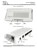
Figure 5
–
RTC Backup Battery Switch
2.
Remove the RTC switch cover shown above and switched on the RTC backup battery switch. Attach
an AC power plug cable to the power adaptor included and connect to the hub’s power jack.
3.
For network connection, connect a RJ45 Ethernet cable (not included) to the Ethernet port of the hub.
Alternatively, the hub can be connected to a wireless network if the Wi-Fi option is present in the hub.
4.
Connect any PanL wired devices to the hub through the RJ45 ports or RJ11 ports. Ensure that the
length of the RJ45 8P8C cables do not exceed 100 Metres from the port to the wired device. In the
event that a single port is used to power* up a few PanL devices in a daisy chain configuration, the
first connection to a PanL device and the subsequent connections between the PanL devices must not
exceed 50 metres in cable length. The total combined cable length must not exceed 100 metres.
*A maximum of 2 PanL devices is allowed for daisy chain if there are more than 1 PD70, PD70PLUS
or PD50 device or any combination of these present. Any other combinations will have a maximum
limit of 3 devices.
For RJ11 port connections, the RJ11 6P4C cable length must not exceed 50 metres from the port to
the PanL device.
5.
Any unused RJ45 ports must be connected to the PanL terminators provided.
6.
PanL wired device connections are depicted below:


