TM
GE60 Installation Manual
580-00505, rev 0.4
30 of 30
PRELIMINARY
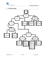
5 Troubleshooting
Is the Supply
voltage at the
radio, with radio
connected,
>+13.5v and
<+24.0v?
Is the Pwr LED
green?
Check the polarity of
the supply voltage.
If polarity of the supply
voltage is correct,
replace radio.
No
Yes
No
Radio link
troubleshooting
process
Check the power supply
output.
Verify the DC cable size
(AWG) is correct for
the actual cable
length.
Is the Fiber LED
green?
Is the RSSI
voltage >
0.2
v?
Is the radio at the
other end of the
link operating and
aligned?
Yes
Yes
Yes
Yes
No
No
No/unsure
Check the fibers to the
radio:
-Swap Tx & Rx fibers
-Network interface is on
-Verify fibers are good
Is the Link Up LED
green?
Is the Pre-FEC
BER voltage >
2.0
v?
Yes
Re-align the radio for
maximum RSSI
voltage
Verify that maximum
path length has not
been exceeded (refer
to Table 2-2)
Verify that both radios
are mounted in same
polarization
Verify that one radio is
Low Band and one is
High Band
No
Check radio at other
end of the link
(Fiber LED should be
solid green)
Check the fibers to the
radio:
-Swap Tx & Rx fibers
-Network interface is on
-Verify fibers are good
Re-align radio using
VAT.
Check radio at other
end of the link.
Does the local
Network
Equipment
indicate good fiber
connectivity?
Yes
Check receive direction
of the radio at other
end of the link.
No
Re-align the radio for
maximum RSSI
voltage
Check for possible
interference by
turning off radio at
other end of link and
verifying that the
RSSI voltage has
dropped below 0.2v
Yes
No

