Not for
Reproduction
74
Cleaning
1.
Tape over governor gear to keep out dirt and debris.
2.
Using a plastic scraping tool, carefully remove old
gasket material from the crankcase and crankcase
cover flanges. Gasket material left on sealing surfaces
will cause leaks.
3.
Remove all carbon deposits from machined surfaces.
Exercise caution to avoid removing any metal material.
For best results, use an air tool with a worn wire brush.
Scraping may result in scratches or nicks.
4.
To soften stubborn deposits, soak the crankcase and
crankcase cover in a suitable chemical solution or other
carbon and gum dissolving agent. Repeat steps 2-3 as
necessary.
5.
Thoroughly clean the crankcase and crankcase cover
in a non-volatile cleaning solution or solvent. Follow up
with a thorough wash in hot soapy water. Blow dry with
low pressure compressed air.
Inspection
1.
Inspect governor gear as follows:
NOTE: Governor gear damage requires crankcase
replacement.
A. Inspect governor gear for worn, cracked, chipped,
or missing teeth.
B. Use your index finger to manually rotate the
governor gear in both directions. Verify that gear
rotates freely without roughness, sticking, or
unusual noise.
C. Spin governor gear to verify that flyweights move
freely.
2.
Using an inside micrometer, check the crankcase and
the crankcase cover camshaft bearing bores for wear.
Replace either part if measurement is 0.553 inches
(14.05 mm) or more.
3.
Check the crankcase for cracks or broken cooling fins.
Check the crankcase cover for cracks. Replace parts
as necessary.
4.
Check for scratches and nicks on all gasket sealing
surfaces. Use a fine-tooth file to carefully remove any
nicks or burrs found.
5.
Check the crankcase and crankcase cover for stripped
threads.
NOTE: Stripped threads can sometimes be repaired
using a helicoil, but replace parts if thread damage is
severe or present at multiple locations.
6.
Inspect the cylinder bore for defects or damage in the
ring travel area. Replace crankcase if the cylinder is
severely scored, scuffed, scratched, burnt, or gouged.
7.
Using Magnaflux Dye Penetrant, inspect the cylinder
bore for cracks. If no cracks are found, thoroughly wash
cylinder to remove traces of dye.
75
8.
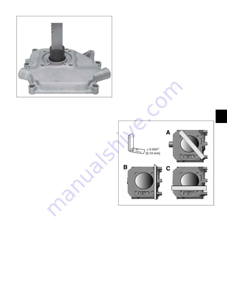
Check the cylinder to cylinder head mating surface for
warpage or distortion. Discard the crankcase if any low
spot is 0.004 inches (0.10 mm) or more. Proceed as
follows:
A. See A of Figure 75. Set a straightedge diagonally
across the length of the cylinder intersecting the
upper and lower corners of the gasket surface.
B. Slide a feeler gauge beneath the straightedge to
check for warpage.
C. Check the opposite diagonal to verify that the
gasket surface is flat.
61
6
Summary of Contents for 130G00
Page 1: ...N o t f o r R e p r o d u c t i o n ...
Page 2: ...N o t f o r R e p r o d u c t i o n ...
Page 6: ...N o t f o r R e p r o d u c t i o n ...
Page 8: ...N o t f o r R e p r o d u c t i o n ...
Page 26: ...N o t f o r R e p r o d u c t i o n 20 2 ...
Page 32: ...N o t f o r R e p r o d u c t i o n 26 3 ...
Page 44: ...N o t f o r R e p r o d u c t i o n TOP END DISASSEMBLY 41 38 5 ...
Page 50: ...N o t f o r R e p r o d u c t i o n 44 5 ...
Page 90: ...N o t f o r R e p r o d u c t i o n 123 84 8 ...
Page 100: ...N o t f o r R e p r o d u c t i o n 94 8 ...
Page 108: ...N o t f o r R e p r o d u c t i o n This page is intentionally left blank 102 9 ...
Page 109: ...N o t f o r R e p r o d u c t i o n This page is intentionally left blank 103 9 ...
Page 110: ...N o t f o r R e p r o d u c t i o n This page is intentionally left blank 104 9 ...
Page 111: ...N o t f o r R e p r o d u c t i o n This page is intentionally left blank 105 9 ...


