6
Assembly
Tube & Ba
ffl
e Assembly
Hardware Installation
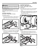
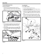
1. On the left side of discharge opening, insert 1/4”-
20x1.25” carriage bolt (
18
, Figure 5) through inside of
mower deck and secure with 1/4”-20 conical nut (
19
) as
shown.
18
19
Figure 5
2. On the right side of discharge opening, insert 5/16”-18
x 1.25” carriage bolt (
24
, Figure 6) through the hole
closest to the discharge opening from the inside of
mower deck.
3. On the outside of mower deck, secure with .341” ID x
1.00” OD washer (
23
), single step spacer (
22
), .33” ID x
1.25” OD washer (
21
) and secure with 5/16”-18 flange
nylock nut (
20
).
22
24
21
23
20
Figure 6
Install Ba
ffl
e
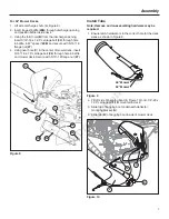
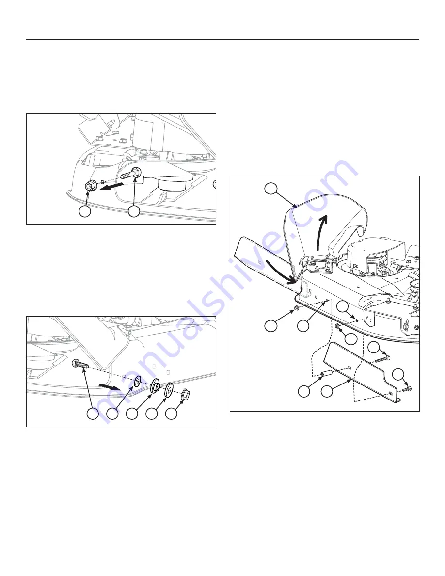
For 46” Mower Decks
1. Lift side discharge chute (
A
, Figure 7).
2. Insert shortest baffle (
28A
) through discharge opening
and position baffle inside deck.
3. Using third hole (
B
) closest to discharge opening, insert
5/16”-18 x 2.0” carriage bolt (
25
) through hole in baffle,
1.32” spacer (
29A
) and secure with 5/16”-18 flange nut
(
27
).
4. Using hole (
C
) near the center of mower deck, insert
5/16”-18 x .75” carriage bolt (
26
) through hole in baffle,
and mower deck. Secure with 5/16”-18 flange nut (
27
).
28A
29A
A
27
25
B
26
C
27
Figure 7
No
t fo
r
Rep
rod
uct
ion


