background image

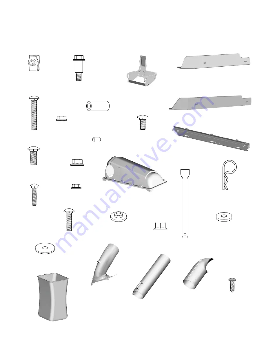
Q

 - CARRIAGE BOLT 

.25” - 20 x 1.25 (Qty. 1)

R

 - NUT 

.25” - 20 (Qty. 1)

T

 - SPACER 

(Qty. 1)

S

 - CARRIAGE BOLT 

.3125” - 18 x 1.25 (Qty. 2)

U

 - WASHER 

.344” ID x 1.00” OD x .160” THK 

(Qty. 1)

V

 - NUT, Nylock

.3125” - 18 (Qty. 1)

W

 - WASHER 

.33” ID x 1.25” OD x .07” THK (Qty. 1)

D

 - BAFFLE, 46” 

(Qty. 1)

G

 - NUT, Whiz Lock

.3125” - 18 (Qty. 2)

J

 - SPACER

.390” ID x .625” OD x .687” LG 

(Qty. 1)

H

 - CARRIAGE BOLT 

.3125” - 18 x .75 (Qty. 1)

E

 - CARRIAGE BOLT 

.3125” - 18 x 2.0 (Qty. 1)

A

 - SPEED NUT

.3125” - 18 (Qty. 2)

B

 - SHOULDER BOLT

.3125” - 18 x 1.62” (Qty. 2)

C

 - UPRIGHT SUPPORT ASSEMBLY

(Qty. 1)

L

 - CARRIAGE BOLT 

.375” - 16 x 1.00 (Qty. 4)

M

 - NUT, Whiz Lock

.375” - 16 (Qty. 4)

K

 -CROSS SUPPORT

(Qty. 1)

N

 - COVER ASSEMBLY

(Qty. 1)

O

 - HINGE PIN 

.375” DIA,  3.75” LG (Qty. 

2)

P

 - HAIR PIN (Qty. 2)

X

 - BAGGING BOOT

(Qty. 1)

Y

 - MIDDLE TUBE

(Qty. 1)

Z

 - UPPER TUBE

(Qty. 1)

AA

 - SCREW

.25”, ABX 75” (Qty. 1)

AB

 - COLLECTOR BAG

(Qty. 3)

Hardware and Parts Identification

  •  Upper case letters identify the hardware and parts in the kit.
  •  Lower case letters identify the existing hardware and parts assembled before the start of the installation.

F

 - SPACER

.392” ID x .625” OD x 1.32” LG 

(Qty. 1)

I

 - BAFFLE, 52” 

(Qty. 1)

4

Not for Reproduction

Summary of Contents for 1696462-00

Page 1: ...62A 00 Triple Bag Grass Collector for 46 52 and 48 Fabricated Deck on Regent and NXT and SPX Mowers Note 1696750 Turbo Kit or 1696672 Bagging Boot Blade and Baffle Kit will be needed for the 48 Fabricated Deck on a Regent Triple Bag Grass Collector Copyright Briggs Stratton Corporation Milwaukee WI USA All rights reserved N o t f o r R e p r o d u c t i o n ...

Page 2: ...indicates an action that could result in damage to the product Hazard Symbols and Meanings Symbol Meaning Safety information about the hazards that can result in personal injury Read the directions for use of the product before operating Keep hands and feet away from deck Thrown object hazard Roll over hazard Manual Contents Operator Safety 2 Hardware and Parts Identification 4 Assembly 5 Operatio...

Page 3: ... the cover while the blades are turning Check the collection system to make sure it is bolted tightly to the unit Collector bags are subject to deterioration and wear during normal use Inspect the bag periodically for tears holes or weak spots and replace with a new bag that meets manufacturer s durability standards WARNING Loss of Control Roll over and Tipping Hazard Use a reduced speed on uneven...

Page 4: ...5 18 x 1 62 Qty 2 C UPRIGHT SUPPORT ASSEMBLY Qty 1 L CARRIAGE BOLT 375 16 x 1 00 Qty 4 M NUT Whiz Lock 375 16 Qty 4 K CROSS SUPPORT Qty 1 N COVER ASSEMBLY Qty 1 O HINGE PIN 375 DIA 3 75 LG Qty 2 P HAIR PIN Qty 2 X BAGGING BOOT Qty 1 Y MIDDLE TUBE Qty 1 Z UPPER TUBE Qty 1 AA SCREW 25 ABX 75 Qty 1 AB COLLECTOR BAG Qty 3 Hardware and Parts Identification Upper case letters identify the hardware and p...

Page 5: ...rt 2 Install the shoulder bolts B into the speed nuts B A a Figure 1 3 Put the upright support assembly C Figure 2 onto the shoulder bolts C Figure 2 Install the Baffles For 46 Mower Decks 1 Put the deflector a Figure 3 in the vertical position 2 Put the baffle D into the discharge opening Attach the left side of the baffle with a carriage bolt E spacer F and a whiz lock nut G E D a G F Figure 3 3...

Page 6: ...e bolt H Figure 6 and a whiz lock nut G Make sure the blade does not come in contact with the baffle H G Figure 6 Install the Cover Support and Cover Assembly 1 Attach the cross support K Figure 7 onto the hitch assembly a with the carriage bolts L and the whiz lock nuts M K L M a Figure 7 2 Put the corner brackets a Figure 8 on the cover assembly N Figure 8 onto the pivot hinges b Install the hin...

Page 7: ...cal nut R Q R Figure 9 Frame Hung Mowers 1 Remove and discard the existing hardware from outside of the right wheel bracket 2 On the inside of the deck insert the carriage bolt S Figure 10 Attach the spacer T washer U and the flange locknut V T S V U Figure 10 Free Floating Mowers 1 On the inside of the deck install carriage bolt S Figure 11 Attach the washer U spacer T washer W and the flange loc...

Page 8: ... deck 3 Slide the top of the bagging boot below the deflector mounting bracket b 4 Slide the tab c of the bagging boot into the mower deck c b a Figure 13 Frame Hung Mowers 1 Rotate the latch a Figure 14 into the space between the spacer and the washer hardware b a b Figure 14 2 Secure the hook c Figure 15 of the mounting strap onto the gage wheel bracket d c d Figure 15 Free Floating Mowers 1 Rot...

Page 9: ...pper tube and middle tube 46 Mower 52 Mower Y AA Z 46 Mower 52 Mower Figure 18 3 Slide the ridge a on the upper tube into the cutout b in the cover assembly N b a N Figure 19 4 Slide the middle tube Y Figure 19 over the bagging boot X Attach the strap c over the pin d d c Figure 19 Install the Collector Bags 1 Put the cover in the vertical position 2 Attach the collector bags AB Figure 21 to the t...

Page 10: ...on Remove all sticks stones or other debris which can get caught or thrown by the mower blades For best results mow when the grass is dry Wet grass can clump and block the mower and grass collector BEFORE YOU BEGIN MOWING make sure the bottom of the mower and the bottom of the catcher cover are clear of grass and debris For satisfactory grass collection air circulation from the mower deck through ...

Page 11: ...se product for purposes of this warranty To ensure prompt and complete warranty coverage register your product at the website shown above or at www onlineproductregistration com Save your proof of purchase receipt If you do not provide proof of the initial purchase date at the time warranty service is requested the manufacturing date of the product will be used to determine the warranty period Pro...

Page 12: ...N o t f o r R e p r o d u c t i o n ...

Reviews: