background image

4

briggsandstratton.com

 WARNING 

Thrown Objects Hazard

Do not open the cover while the blades are turning.

• Check the catcher system to make sure it is bolted

tightly to the unit.

• Catcher bags are subject to deterioration and wear

during normal use. Inspect the bag periodically for

tears, holes, or weak spots and replace with a new bag

that meets manufacturer’s durability standards.

 WARNING 

Loss of Control, Roll-over and Tipping Hazard

• Use reduced speed on uneven ground and when

turning corners.

• Reduce loads on hillsides. It is recommended that the

catcher system be kept only half full when mowing any

slope. Start mowing on slopes when the catcher system

is empty.

• Mow on the face of slopes as directed in the operator’s

manual and safety warnings on the product.

• Never operate on slopes greater than 17.6% (10°).
• Select a slow ground speed before driving onto a slope.

Avoid using brakes to control speed.

• Use caution when changing directions and DO NOT

start or stop the rider while on a slope.

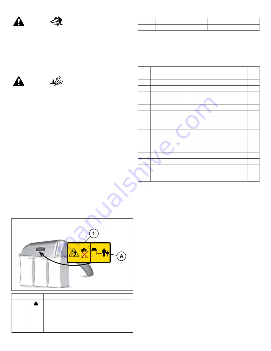
Safety Decals - Triple C

atche

r

Before operating the grass catcher, read and understand the


installed safety decals. The decals are provided to help you


avoid personal injury or damage to the product. 
If any safety decals become damaged or illegible, order


replacements from your local authorized dealer. See Figure 1.

1

Callout Hazard

Description

1

Thrown Object Hazard

Do not open the 

catche

r while the mower blades are


turning.
Do not operate the mower without the complete grass


c

atche

r in place. Keep bystanders and children a safe


distance.

Callout

Hazard

Part Number

A

Thrown Objects Hazard

7104709

Hardware and Parts - Grass

Catcher

See Figure 2.

CALL

OUT

DESCRIPTION

SPECIFICATION

QTY.

A

SIDE PLATE

-

2

B

CAPSCREW

.375”-16 x 1.00”

4

C

LOCK NUT, Flange

.375”-16

4

D

CAPSCREW

.50”-13 x 2.50”

4

E

WASHER

.531” ID x 1.25” OD x .08” THK

4

F

SPACER

.52” ID x .73" OD x 1.27"

4

G

NUT, Nylock

.50”-13

4

H

CARRIAGE BOLT

.375”-16 x 1.0"

4

I

FLANGE NUT,

Whiz-Lock

.375”-18

4

J

COVER HINGE PIN

-

2

K

HAIR PIN

-

2

L

CROSS SUPPORT

-

1

M

COVER ASSEMBLY

-

1

N

CATCHER BAG

-

3

O

UPRIGHT SUPPORT

ASSEMBLY

-

1

Refer to the chart for the callouts, descriptions, specifications

and quantities.

Not for 

Reproduction

Summary of Contents for 1697363A-00

Page 1: ... Briggs Stratton LLC Milwaukee WI USA All Rights Reserved 80099036 Revision A N o t f o r R e p r o d u c t i o n ...

Page 2: ...als Triple Catcher 4 Hardware and Parts Grass Catcher 4 Installation 5 Install the Side Plates 5 Install the Mounting Spacers 5 Install the Upright Support Assembly 7 Install the Cross Support Catcher Bags and Cover Assembly 8 Install the Catcher Boot Kit Turbo Kit 8 Operation 8 Storage 9 Briggs Stratton PRODUCTS Warranty Policy 10 Grass Catcher Templates 10 N o t f o r R e p r o d u c t i o n ...

Page 3: ...fety information about the hazards that can result in personal injury Read the directions for use of the product before operating Symbol Meaning Keep hands and feet away from deck Thrown object hazard Roll over hazard Safety Warnings Grass Catchers WARNING Failure to read and follow the safety warnings and instructions in this document and in the rider operator s manual could result in death serio...

Page 4: ...le on a slope Safety Decals Triple Catcher Before operating the grass catcher read and understand the installed safety decals The decals are provided to help you avoid personal injury or damage to the product If any safety decals become damaged or illegible order replacements from your local authorized dealer See Figure 1 1 Callout Hazard Description 1 Thrown Object Hazard Do not open the catcher ...

Page 5: ...bar before the removal and installation of the hardware on the right side Install the Side Plates Broadmoor 1600 2600 LT Series CTX 9000 Use the Hardware Parts Bag AA 1 Attach the side plate A Figure 3 to the side of the frame with the capscrews B and flange locknuts C Repeat for the other side 3 Install the Mounting Spacers Broadmoor without Suspension 1600 2600 LT Series CTX 9000 Models Use the ...

Page 6: ...S NOT INCLUDE the spacers continue with Step 2 6 2 Remove and discard the existing hardware b Figure 7 from the UPPER mounting hole on the left side of the frame Repeat for the other side 7 Note If there are NO holes for installation refer to Section Grass Catcher Templates for the instructions and template 3 Install the capscrews D Figure 8 washers E spacers F and nylock nuts G Repeat for the oth...

Page 7: ...the LOWER mounting hole Note If there are NO holes for installation refer to Section Grass Catcher Templates for the instructions and template Repeat for the other side 12 Install the Upright Support Assembly Broadmoor without Suspension 1600 2600 LT Series CTX 9000 Models 1 Put the upright support assembly O Figure 13 on the spacers F 13 Broadmoor with Suspension 1600 2600 LT Series CTX 9000 Mode...

Page 8: ...abs a on the cross support assembly 17 Attach the Cover Assembly Use Hardware Parts Bag CC 1 Put the corner brackets a Figure 18 on the cover assembly M onto the pivot hinges b Install the hinge pins J and hair pins K 18 Install the Catcher Boot Kit Turbo Kit WARNING DO NOT operate the unit without either the entire grass catcher or the deflector in place Install the catcher boot kit or turbo kit ...

Page 9: ...ock the mower and the grass collector BEFORE YOU BEGIN MOWING make sure the bottom of the mower and the bottom of the cover assembly are clear of grass and debris For satisfactory grass collection air circulation from the mower deck through the chute and into the grass catcher is very important Make sure there are tight connections between the mower deck turbo housing tubes and the cover assembly ...

Page 10: ...y but sometimes requests for warranty service may not be appropriate This warranty covers only defects in materials or workmanship It does not cover damage caused by improper use or abuse improper maintenance or repair or normal wear and tear Improper Use and Abuse The proper intended use of this product is described in the Operator s Manual Using the product in a way not described in the Operator...

Page 11: ...each template with the side of the rear frame support a Figure 23 and attach with tape 23 3 Put a mark in the center of the holes 4 Drill the holes on each side with a 17 32 drill bit N o t f o r R e p r o d u c t i o n ...

Page 12: ...N o t f o r R e p r o d u c t i o n ...

Reviews: