background image

Battery Maintenance

Cleaning the Battery and Cables

1. Disconnect the cables from the battery, negative cable first

(A, Figure 8).

2. Remove the battery hold-down (C) and battery.

3. Clean the battery compartment with a solution of baking

soda and water.

4. Clean the battery terminals and cable ends with a wire brush

and battery terminal cleaner until shiny.

5. Reinstall the battery in the battery compartment, and secure

with the battery hold-down (C).

6. Reattach the battery cables, positive cable first (B). 

7. Coat the cable ends and battery terminals with petroleum

jelly or non-conducting grease.

Figure 8.  Battery
A. Negative Cable
B. Positive Cable & Cover
C. Rubber Hold-Down Strap

A

C

B

WARNING

When removing or installing battery cables, disconnect
the negative cable FIRST and reconnect it LAST. If not
done in this order, the positive terminal can be shorted
to the frame by a tool.

Safety Interlock System Check

Check the function of the safety interlock system using the test
procedur. If the tractor fails any of the tests, see your dealer.

Blade Brake Check

Mower blades and mower drive belt should come to a complete
stop within five seconds after the electric PTO switch is
turned off.

1. With tractor in neutral, PTO disengaged and operator in

seat, start the engine.

2. Look over the left-hand footrest at the mower drive belt.

Engage the PTO and wait several seconds. Disengage the
PTO and check the amount of time it takes for the mower
drive belt to stop.

3. If mower drive belt does not stop within five seconds, see

your dealer.

Engine Maintenance

Refer to the engine owner’s manual for all engine maintenance
procedures and recommendations.

21

Regular Maintenance

Not 

for  

Reproduction

Summary of Contents for 2609762

Page 1: ...CE 2690763 Snapper RD21V40 21HP w 40 Mower CE 2690772 Massey Ferguson 2421 XL 20HP w 40 Mower CE 2690773 Simplicity Baron XL 21HP 4WD w 40 Mower CE 2690774 Snapper RD21V40 21HP 4WD w 40 Mower CE Baro...

Page 2: ...N o t f o r R e p r o d u c t i o n...

Page 3: ...28 NOTE In this manual left and right are referred to as seen from the operating position Safety Rules Information 4 Identification Numbers 9 Safety Decals 10 Safety Icons 11 Features Controls 12 Ope...

Page 4: ...d maintenance information is included to help you get the most out of your equipment investment Be sure to completely read the Safety Rules and Information found on the following pages Also completely...

Page 5: ...rator present safety system Do NOT attempt to alter or bypass the system See your dealer immediately if the system does not pass all the safety interlock system tests found in this manual Thrown Objec...

Page 6: ...ponsible for accidents occurring to other people or property 21 All drivers should seek and obtain professional and practical instruction 22 Always wear substantial footwear and trousers Never operate...

Page 7: ...a slope If tires lose traction disengage the blade s and proceed slowly straight down the slope 7 Keep all movement on slopes slow and gradual Do not make sudden changes in speed or direction which c...

Page 8: ...rther than necessary Ensure clamps grip hoses firmly over the filter after installation 12 Do not use gasoline containing METHANOL gasohol containing more than 10 ETHANOL gasoline additives or white g...

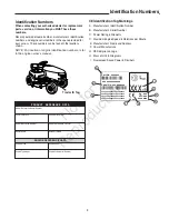
Page 9: ...er Dealer Name Date Purchased Engine Make Engine Type Spec Engine Model Engine Code Serial Number Mower Deck MFG Number Mower Deck SERIAL Number CE Identification Tag Markings A Manufacturer s Identif...

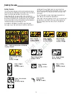
Page 10: ...important The safety decals below are on your rider and mower If any of these decals are lost or damaged replace them at once See your local dealer for replacements These labels are easily applied an...

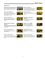
Page 11: ...e the with the hopper removed or without the deflector Danger Thrown Objects Do not operate without first connecting the discharge tube Danger Dismemberment This machine can amputate limbs Keep bystan...

Page 12: ...e forward to increase engine speed and back to decrease engine speed Always operate at FULL throttle Choke Close the choke for cold starting Open the choke once the engine starts A warm engine may not...

Page 13: ...verse ground speed is controlled by the reverse ground speed control pedal Depressing either pedal will increase ground speed Note that the further down the pedal is depressed the faster the tractor w...

Page 14: ...to lock the parking brake when the tractor is stopped Fully depressing the brake pedal and pulling up on the knob engages the parking brake Catcher Dump Lock Pedal The catcher dump lock pedal unlocks...

Page 15: ...the engine owner s manual provided in the operator s packet shipped with your tractor Follow any recommended stopping procedures 4 Turn the ignition switch to OFF Remove the key WARNING Gasoline is hi...

Page 16: ...e tractor will travel 7 Stop the tractor by releasing the ground speed control pedals setting the parking brake and stopping the engine see STOPPING THE TRACTOR AND ENGINE Mowing 1 Set the mower cutti...

Page 17: ...lease the parking brake fully depress the brake pedal B and push the parking brake knob C DOWN A B C A B Four Wheel Drive Models 4WD 1 Disengage the PTO and turn the engine off 2 Push the transmission...

Page 18: ...Emptying the Hopper A Catcher Dump Pedal B Catcher Lever C Catcher Lock Knob 3 4 1 2 A C B Attaching a Trailer NOTE Remove the hopper to attach a trailer The maximum horizontal drawbar force allowed i...

Page 19: ...ual This includes draining the fuel system or adding stabilizer to the fuel do not store a fueled unit in an enclosed structure see above Battery life will be increased if it is removed put in a cool...

Page 20: ...r blade stopping time Check tractor and mower for loose hardware Check tire pressure Every 50 Hours or Annually Check tractor brakes Clean battery and cables See Dealer Annually to Lubricate tractor a...

Page 21: ...tive cable FIRST and reconnect it LAST If not done in this order the positive terminal can be shorted to the frame by a tool Safety Interlock System Check Check the function of the safety interlock sy...

Page 22: ...l not depressed Fully depress brake pedal PTO electric clutch switch is in ON position Place in OFF position Cruise control engaged Move knob to NEUTRAL OFF position Out of fuel If engine is hot allow...

Page 23: ...er cut is uneven Mower not leveled properly See authorized dealer Tractor tires not properly inflated See Check Tire Pressure Mower cut is rough looking Engine speed too slow Set to full throttle Grou...

Page 24: ...p increases the volume of grass in the collector before the alarm goes off Sliding the paddle bracket C down decreases the volume of grass in the collector before the alarm goes off 1 Loosen bracket h...

Page 25: ...Adjustments WARNING Keep open flames and sparks away from the battery the gasses coming from it are highly explosive Ventilate the battery well during charging Mower Lift Adjustment Mower lift height...

Page 26: ...is requested the manufacturing date of the product will be used to determine warranty eligibility ABOUT YOUR WARRANTY We welcome warranty repair and apologize to you for being inconvenienced Warranty...

Page 27: ...t Top of Seat 44 in 112 cm Weight approx 21HP Tractor 707 7 lbs 321 kg The gross power rating for individual gas engine models is labeled in accordance with SAE Society of Automotive Engineers code J1...

Page 28: ...e Parts Engine Oil Touch Up Paint Grease Gun Kit 8 oz Grease Tube Tire Sealant Degrimer Degreaser Gas Stabilizer Maintenance Items Many convenient and helpful service and maintenance items are availab...

Page 29: ...N o t f o r R e p r o d u c t i o n...

Page 30: ...N o t f o r R e p r o d u c t i o n...

Page 31: ...N o t f o r R e p r o d u c t i o n...

Page 32: ...w snapper com Briggs Stratton Power Products Group L L C Copyright 2010 Briggs Stratton Corporation Milwaukee WI USA All Rights Reserved www BRIGGSandSTRATTON com www SimplicityMfg com N o t f o r R e...

Reviews: