Not for
Reproduction
21
• Less spring pre-load should be used with light weight
operators, which will provide a softer, more cushioned
ride.
• More spring pre-load should be used with heavy weight
operator's , which will provide a stiffer, more rigid ride.
• There are three positions in which the upper shock mount
can be positioned in. If adjusting the spring pre-load
does not achieve the ride requirement, the shock should
be moved to the next numbered upper shock mounting
position to achieve the desired ride requirement.
• Before adjusting the upper shock mount to a higher
numbered position, you should attempt to achieve the
ride height through the spring pre-load adjustment.
• Shock mounting position #3 should always be used when
a rear mounted grass collection system is installed on the
unit.
To Adjust the Spring Pre-load:
1. Park the machine on a flat, level surface. Disengage the
PTO, stop the engine, and engage the parking brake.
2. Chock the front wheels to prevent the machine from
rolling. Raise the rear of the machine and secure with
jack stands.
3. Remove the rear drive tires.
WARNING
Spring loaded components can kick back causing injury.
Use two hands when adjusting the shock springs. This will
prevent the wrench from slipping while pressure is being
applied.
4. Using the supplied spanner wrench (p/n 5022853) (B,
Figure 46), insert the tip of the wrench into the notch in
the pre-load adjuster. While holding the wrench in place
with one hand, turn
counter-clockwise
to increase the
pre-load, turn
clockwise
to decrease the pre-load. Make
sure both shocks are set to the same amount of pre-load.
5. Re-install the rear drive tires. Torque the lug bolts to
85-95 ft.lbs. (115-129 Nm). Remove the jack stands from
under the machine.
Note:
If a collection system is installed on the unit it is
recommended that the rear suspension be adjusted stiffer
due to the added weight of the collection system.
To Adjust the Upper Mounting Position (Rear
Shocks):
1. Park the machine on a flat, level surface. Disengage the
PTO, stop the engine, and engage the parking brake.
2. Chock the front wheels to prevent the machine from
rolling. Raise the rear of the machine and secure with
jack stands. The jack stands must be under the bumper
of the machine.
3. Position the jack underneath the rear cross member
of the transmission cradle and slowly raise the rear
suspension to relieve the pressure on the upper shock
mounting bolts.
4. Remove the upper shock mounting hardware and pivot
the shock to the next higher numbered position (see
Figure 46). Adjust the jack to align the shock mounts to
shocks.
5. Remove the jack from under the transmission cradle.
6. Remove the jack stands from underneath the machine.
Parking Brake Adjustment
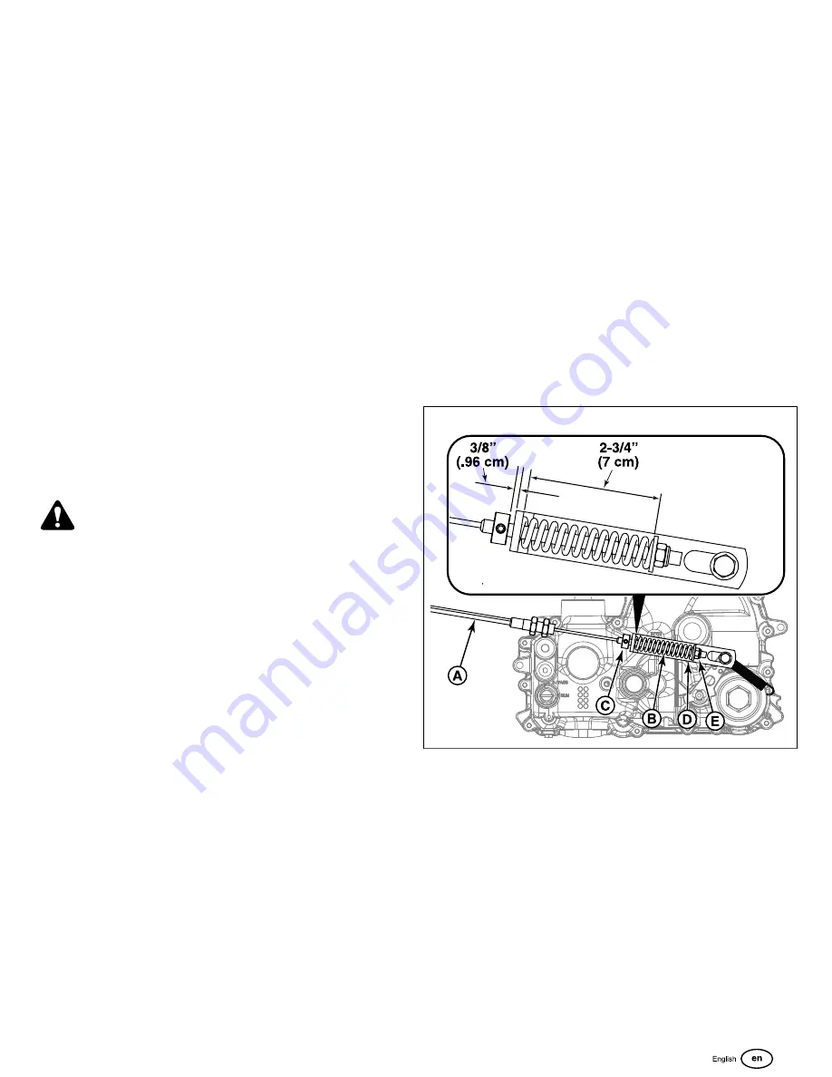
The parking brake mechanism consists of two parking brake
cables (A, Figure 47) that connect the parking brake lever
shaft to the parking brake control arm on the transmissions.
There is a parking brake spring on each parking brake cable
located below the engine deck by the transmission. The
position of the parking brake cable in the rear suspension
cradle is factory preset and should not be changed for parking
brake adjustment procedures. The adjustment is achieved by
changing the compressed spring length of the parking brake
springs.
47
1. Disengage the PTO, engage the parking brake, stop the
engine, and chock the tires.
2. Locate the parking brake springs (B) by the
transmissions.
3. With the parking brake engaged measure the
compressed spring length. The spring should measure
2-3/4" (7 cm) when compressed.
4. If the spring length does not equal the measurement, the
spring length will need to be adjusted.
5. Disengage the parking brake.
6. Loosen the set collar (C) and slide it away from the back
of the parking spring bracket (D).

