1
5
1
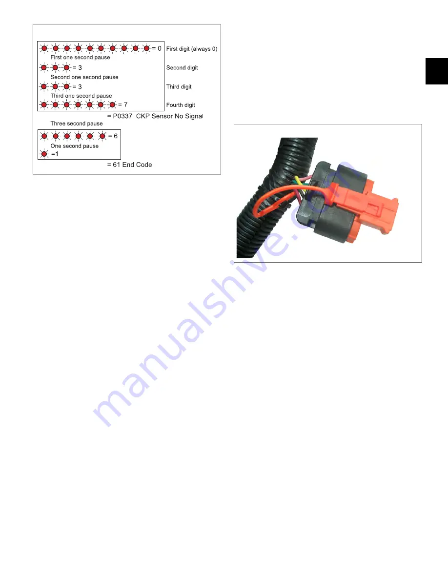
6. Count the number of flashes after the first one second
pause to obtain the second digit of the DTC.
7. Count the number of flashes after the second one
second pause to obtain the third digit, and then count
the number of flashes after the third one second
pause to obtain the fourth digit.
8. Write down each digit as it is displayed.
9. If there is more than one DTC, the next DTC begins
to flash after a three second pause.
10. After all DTCs are reported, the number “61” is
flashed to indicate this condition to the technician.
The flashing sequence is then restarted and the
technician may choose to verify the DTCs written
down or exit the routine.
NOTE:
If “61” is the first code flashed, then no active
DTCs are set.
Use Tiny Scan Code Reader to Read/Clear
DTCs
NOTE:
Always follow steps 1-9 for an accurate report of
current DTCs. Failure to do so may generate a report that
includes historic codes.
1. Obtain Briggs & Stratton Tiny Scan Code Reader
(Part No. 19626).
2. Connect code reader to DLC.
3. Turn Ignition ON, Engine OFF.
NOTE:
If the Tiny Scan Code Reader cannot connect
to the ECM, “no-C” is displayed, which stands for “no
communication.” If communication is established, the
tool displays the number of DTCs read. For example,
“dc-0” means that no DTCs were found, while “dc-4”
means that four DTCs are recorded.
4. Press the select button to cycle through the list of
DTCs.
5. Once the last DTC is displayed, “CLr?” appears.
Press and hold the select button until “Hold” changes
to “Done,” which indicates that all DTCs have been
“cleared” from ECM memory.
6. Turn Ignition OFF for a minimum of 20 seconds.
7. Turn Ignition ON, Engine OFF.
8. The tool displays the number of DTCs read.
9. Press the select button to cycle through the list of
DTCs. Write down each DTC as it is displayed.
2
Use Diagnostic Tool to Read/Clear DTCs
1. Obtain Briggs & Stratton Diagnostic Tool (Part No.
19636) with USB and Interface cables.
2. Connect one end of the USB cable to the Diagnostic
Tool and the other end to the USB port on the laptop.
3. Connect one end of the Interface cable to the
Diagnostic Tool and the other end to the DLC on the
EFI harness.
4. Turn Ignition ON, Engine OFF. The Diagnostic Tool
can take up to 30 seconds to connect to the engine.
5. See Figure 3. Select the
Dashboard
icon (
A
) in the
left sidebar to view the
Dealer
tab.
6. Observe the Current codes display (
B
).
NOTE:
The
CHECK ENGINE
light (
C
) is green if a
current fault code is present. To display a description
of the fault code, hover the cursor over the code.
NOTE:
A Current codes display can also be viewed
under the
Troubleshooting
tab.
7. Click
Clear
(
D
) to erase both current and historic
DTCs.
NOTE:
See the Briggs & Stratton EFI Diagnostic Tool
Software User Manual for more information.
8. Turn Ignition OFF.
Not for
Reproduction
Summary of Contents for VANGUARD M490000
Page 2: ...N o t f o r R e p r o d u c t i o n ...
Page 6: ...N o t f o r R e p r o d u c t i o n ...
Page 84: ...3 80 MODEL 490000 EFI ELECTRICAL SCHEMATIC PAGE 1 OF 2 N o t f o r R e p r o d u c t i o n ...
Page 85: ...3 81 MODEL 490000 EFI ELECTRICAL SCHEMATIC PAGE 2 OF 2 N o t f o r R e p r o d u c t i o n ...
Page 95: ...3 91 MODELS 490000 540000 610000 FUSE RELAY BLOCK N o t f o r R e p r o d u c t i o n ...
Page 96: ...3 92 N o t f o r R e p r o d u c t i o n ...
Page 110: ...4 106 N o t f o r R e p r o d u c t i o n ...
Page 115: ...5 111 This page is intentionally left blank N o t f o r R e p r o d u c t i o n ...
Page 134: ...5 130 30 N o t f o r R e p r o d u c t i o n ...
Page 137: ...5 133 This page is intentionally left blank N o t f o r R e p r o d u c t i o n ...
Page 138: ...5 134 32 N o t f o r R e p r o d u c t i o n ...
Page 140: ...5 136 33 N o t f o r R e p r o d u c t i o n ...
Page 142: ...5 138 This page is intentionally left blank N o t f o r R e p r o d u c t i o n ...


