background image

5

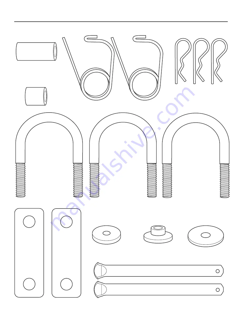
Hardware Bag Contents

N

 - SPACER, 

.392” ID x .625” OD x .1.32” LG 

(Qty. 1)

O

 - SPACER, 

.390” ID x .625” OD x .687” LG 

(Qty. 1)

P

 - SAFETY CLIP, 

(Qty. 2)

Q

 - HAIR PIN, 

(Qty. 3)

R

 - U-BOLT, 

3/8”-16 x 1.125” (Qty. 3)

S

 - SPACER, 

(Qty. 2)

T

 - WASHER, 

.34” ID x 1.00” OD x .13” THK 

(Qty. 1)

U

 - SPACER, 

SINGLE STEP

(Qty. 1)

V

 - WASHER, 

.033” ID x 1.25” OD x .07” THK

(Qty. 1)

W

 - COVER HINGE PIN, 

(Qty. 2)

No

t fo

r  

Rep

rod

uct

ion

Summary of Contents for ZT

Page 1: ...ATTACHMENT OPERATOR S MANUAL Mfg No Description 5600355 ZT Triple Bagger 1739740 Rev C Triple Bagger N o t f o r R e p r o d u c t i o n ...

Page 2: ...2 N o t f o r R e p r o d u c t i o n ...

Page 3: ...tallation 9 Bag Cover Support Installation 9 Attach Collector Bags 10 Mower Mounting Hardware Installation 10 Tube Assembly 11 Cover Assembly 12 Assemble Upper Middle Tube 12 Operation 13 Operation 13 Collector Removal 14 Storage 14 Warranty 15 NOTE In these instructions left and right are referenced from the operat ing position Assembly N o t f o r R e p r o d u c t i o n ...

Page 4: ... Qty 1 I NUT 1 2 13 Qty 2 J NUT FLANGE 3 8 16 Qty 6 K NUT FLANGE 3 8 16 Qty 4 L NUT CONICAL 1 4 20 Qty 1 M NUT 5 16 18 Qty 1 C CARRIAGE BOLT 5 16 18 x 1 25 Qty 2 D CAPSCREW 1 2 13 x 1 35 Qty 2 E CAPSCREW 3 8 16 x 1 0 Qty 4 F CARRIAGE BOLT 1 4 20 x 1 25 Qty 1 G SCREW 1 4 x 75 Qty 1 N o t f o r R e p r o d u c t i o n ...

Page 5: ...0 ID x 625 OD x 687 LG Qty 1 P SAFETY CLIP Qty 2 Q HAIR PIN Qty 3 R U BOLT 3 8 16 x 1 125 Qty 3 S SPACER Qty 2 T WASHER 34 ID x 1 00 OD x 13 THK Qty 1 U SPACER SINGLE STEP Qty 1 V WASHER 033 ID x 1 25 OD x 07 THK Qty 1 W COVER HINGE PIN Qty 2 N o t f o r R e p r o d u c t i o n ...

Page 6: ...F UPRIGHT SUPPORT Qty 1 AG HITCH ROD Qty 1 AI COLLECTOR BAGS Qty 3 AH BAG COVER SUPPORT Qty 1 AJ BAGGING BOOT Qty 1 AK COVER ASSEMBLY Qty 1 AL MIDDLE TUBE Qty 1 AM UPPER TUBE Qty 1 CHUTE Qty 1 NUT LOCK 10 24 Qty 1 WASHER 20 ID x 50 OD x 05 THK Qty 2 USE WITH TURBO See Turbo Manual SCREW 10 24 x 75 Qty 1 N o t f o r R e p r o d u c t i o n ...

Page 7: ...rning Do not operate the mower without the complete catcher in place WARNING 1732819 Read these safety rules and follow them closely Failure to obey these rules could result in loss of control of unit severe personal injury or death to you or bystanders or damage to property or equipment The triangle in text signifies important cautions or warnings which must be followed GENERAL WARNING Know the u...

Page 8: ... insert carriage bolt A through hole in baffle spacer N and mower Secure with nut H 4 Using hole near the center of mower deck insert carriage bolt B through hole in baffle and mower deck Secure with nut H AA A N H H B Figure 1 For 52 Mower Decks 1 Lift side discharge chute Figure 2 2 Insert baffle AB through discharge opening and position inside deck 3 Using hole closest to discharge opening inse...

Page 9: ... spacers S around the bottom bumper tube and install hitch plate through the lower middle holes Secure with two nuts J 3 Insert two u bolts R through middle bumper tube and secure to hitch plate through middle holes with four nuts J AE J R R S Figure 4 4 Set the upright support AF Figure 5 onto pins of hitch plate AE Insert rod AG and secure with hair pin Q as shown AF AG AE Q Figure 5 Bag Cover S...

Page 10: ...ion For non turbo use only 1 On the back side of discharge opening insert carriage bolt F Figure 8 through inside of mower deck and secure with nut L F L Figure 8 Frame Hung Mowers 1 Remove existing hardware from outside of the front right wheel bracket Figure 9 2 Replace with carriage bolt C spacer U washer V and secure with nut M as shown V U M C Figure 9 Free Floating Mowers 1 From the inside o...

Page 11: ...ing boot underneath deflector mounting bracket Note The deflector mounting bracket hardware may need to be loosened for this step Retighten hardware after installing bagging boot 4 Slide tab of bagging boot inside of mower deck F AJ Figure 12 Frame Hung Mowers 1 Rotate latch Figure 13 into pocket of hardware assembly Figure 13 2 Secure hook Figure 14 of mounting strap onto wheel bracket Figure 14 ...

Page 12: ...e Upper Middle Tube For non turbo use only 1 Slide middle tube AL Figure 18 into upper tube AM 2 See Figure 18 for correct hole location and secure the upper tube to middle tube using screw G through hole G 46 Mowers 52 Mowers AM AL Figure 18 3 Slide the upper and middle tube Figure 19 into cover AK aligning ridge with cutout as shown AK Figure 19 4 Slide middle tube AL Figure 20 over bagging boot...

Page 13: ... snug fit between mower deck blower housing tubes and grass catcher cover Mowing with the Catcher Always operate with throttle at full speed when mowing Grass should be cut often and not too short If grass is too long or lush it may be necessary to keep ground speed to a minimum or to cut only half the width of the mower to prevent clogging If grass is long operate with mower in high cutting posit...

Page 14: ...ctor Rotate latch upward on front of bagging boot 5 Remove mounting strap from rear bracket and pull bagging boot away from mower 6 Remove baffle AA AB Figure 21 Storing The Grass Catcher Clean the grass catcher thoroughly using a mild detergent other products may damage the tube Remove any debris from the screen on the underside of the lid If paint has been scratched on metal parts touch up with ...

Page 15: ...of purchase receipt If you do not provide proof of the initial purchase date at the time warranty service is requested the manufacturing date of the product will be used to determine warranty eligibility We welcome warranty repair and apologize to you for being inconvenienced Warranty service is available only through servicing dealers authorized by Briggs Stratton or BSPPG LLC Most warranty repai...

Page 16: ...Briggs Stratton Yard Power Products Group Copyright 2011 Briggs Stratton Corporation Milwaukee WI USA All Rights Reserved N o t f o r R e p r o d u c t i o n ...

Reviews: