background image


©Copyright  

 FR-V2016 

Les informations contenues dans ce document peuvent être modifiées sans préavis. 


Fig 4 – Clamp Saddle 

4.2


Electrical Installation 

4.2.1


Instalattion of Electrolysis Cell  

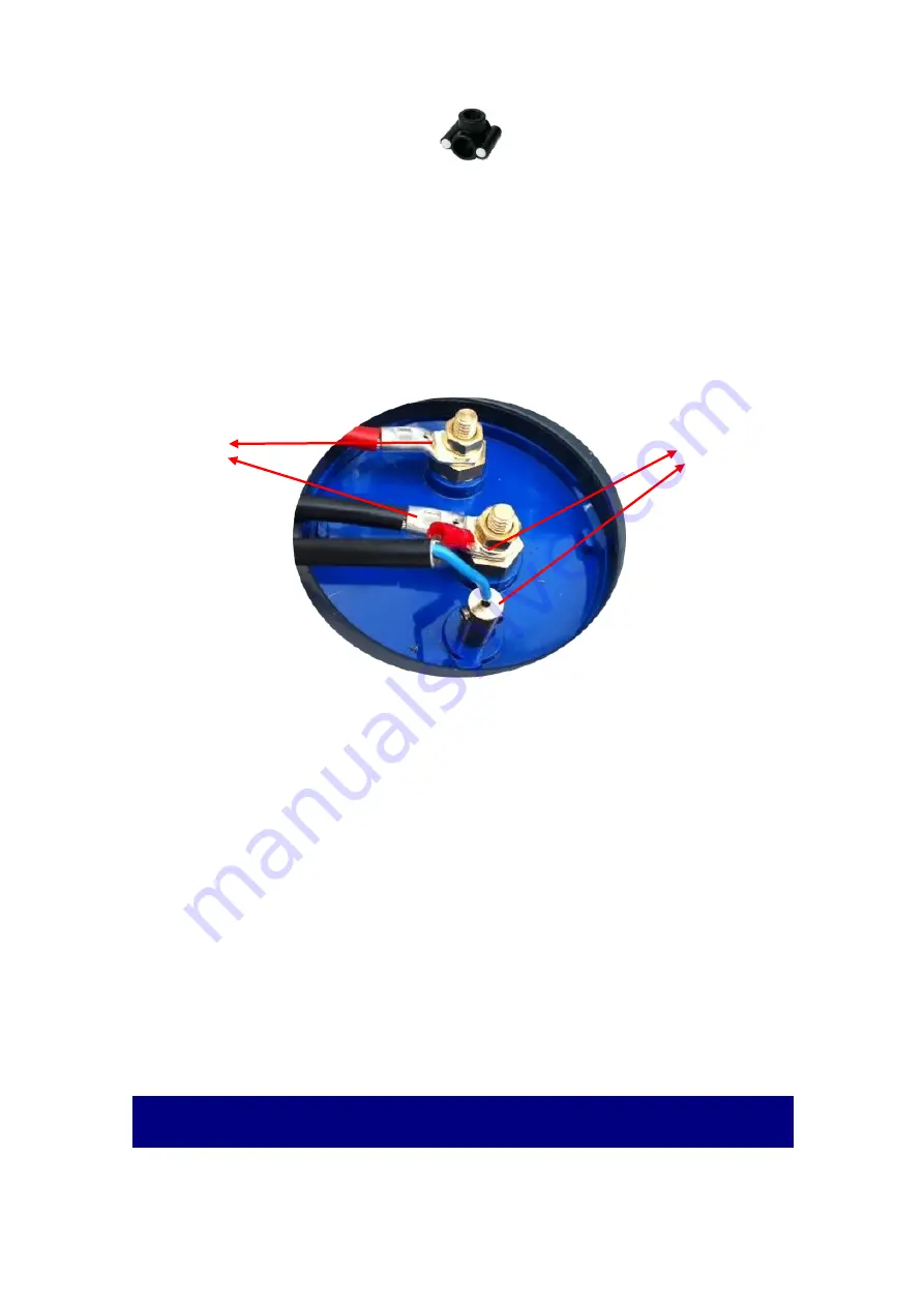
The connection to the electrolysis cell is done through two conductors of 6 to 10mm2 

(depending on the cell power) and two conductors of 0.75mm2, both supplied with the system. 
One of the 0.75mm2 conductors has one M3 terminal, the remaining conductors have two M6 
terminals which must be connected to the corresponding terminals in the cell (see Figure 5). 


Fig 5 – Electrolysis Cell Connection Terminals 


4.2.2


Installation of Temperatura Probe (Optional) 

The temperature probe connects to the bottom of the equipment in the indicated plug 

(2.5mm Jack plug located under the left side).External Controller Instalattion (optional). 

4.2.3


External Controller Installation (Optional) 


If you choose to connect an external controller, it must emit a potential-free signal which 

must  be  transmitted  to  the  COLIBRI  via  specific  cable  (consult  the  manufacturer),  which  is 
connected to the equipment in the connector indicated on the lower part of the equipament. 
 

4.2.4


Automatic Coverage Detector Installation (optional) 

If the pool has an automatic cover system, it can be connected to the COLIBRI so that it 

detects if the cover is open or closed. The connection must be made via a separate specific cable 
(consult the manufacturer), which is connected to the equipment in the connector indicated on 
the bottom of the equipment. 

5


Operation 


IMPORTANT NOTICE: The equipment should only be connected in conjunction with the 

circulation pump or when the circulation pump is already switched on. 

Gas detector 

Electrolysis  

Cell Power 

Summary of Contents for COLIBRI RX

Page 1: ...COLIBRI RX PLUMA RX SALT CHLORINATOR...

Page 2: ......

Page 3: ...al Probe 7 5 5 Operation with Pool Coverage 7 5 6 Disinfection Recommendations 8 6 Configuration and Calibration 8 6 1 Current Calibration 8 6 2 ORP Calibration 9 6 3 Setting ORP Limits 10 6 4 Polarit...

Page 4: ...oller s door open to stabilize temperature and avoid condensation of the electronic components When the controller is turned on remember to let the capacitors discharge before handling them to avoid e...

Page 5: ...ell can be installed horizontally or vertically In the vertical installation the electrical wires must be faced upwards to allow for the buildup of gases originated from the electrolysis process on th...

Page 6: ...d under the left side External Controller Instalattion optional 4 2 3 External Controller Installation Optional If you choose to connect an external controller it must emit a potential free signal whi...

Page 7: ...olysis as a percentage of filtering time in order to increase or decrease production and always choose the best reality of the swimming pool in which the equipment is installed Pressing the control bu...

Page 8: ...l time chlorine readout ORP _____ mV is displayed on the machine s display In this mode chlorine production should be set to P100 and ORP limits for the range that best fits the pool reality where the...

Page 9: ...nstallation If you wish to change the factory settings or need to calibrate the ORP current or probe proceed as described in the following chapters To enter the Setup Calibration menu move the side sw...

Page 10: ...have all the necessary material including a glass of water and absorbent paper in order to clean the probe before introducing the buffers To enter the ORP calibration select the C O option in the Cali...

Page 11: ...its To set the limits briefly press the Command Button and appears Figure 15 Definition of Upper Limits To change the value briefly press the Command Button to set the desired limit The upper limit ca...

Page 12: ...or a few seconds then stop tp reverse and stars again on the other polarity 7 Alarms 7 1 Alarm 1 Low Flow This alarm ALARM 1 is released if there is not sufficient water flow in the electrolysis cell...

Page 13: ...arm 3 Low ORP This alarm ALARM 3 is triggered when the ORP reading is greater than 0mV and less than 150mV and is used to indicate that the chlorine level in the water is too low or that the ORP probe...

Page 14: ...lysis cell 5 years for the electronic equipment Twelve months for temperature probes except ware out PLUMA 2 years or 10 500h of operation for the electrolysis cell 2 years for the electronic equipmen...

Page 15: ...s and investment in its country Bright Blue does not take responsibility for any delay or fault caused by circumstances outside its control Possible situation include but are not limited to interrupte...

Reviews: