background image

1P128

Assembly - Right End Seedshaft & Bearing

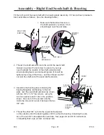
Fit the right end of the seed shaft with the bearing plate assembly.  If it has not been preassem-
bled, assemble as follows:  (See the drawings below.)

3.  Assemble the bearing plate containing the 

bearing flangettes and bearing to the end 
plate  over the seed shaft extension as shown, 
with two 3/8” x 3-1/2” tap screws,  using the 
two lock washers and 7 nuts in the positions 
shown.  Be sure to fit the pointer onto the 
inside tap screw and secure it between the two 
3/8” nuts.

1.  Make sure the Number Decal is on 

the shaft extension; numbers  0 to 8 
should begin near the end plate.

2.  Thread  the shaft extension onto the end of the seed shaft, 

loosely snug down the set screw to secure it (you may 
need to adjust the position of the shaft extension later 
when adjusting feed cups and seeding rate (it should be 
tightened securely at that time),  and then thread one 5/8” 
nut onto the shaft end of the seed shaft extension.

4.  Thread the other 5/8” nut onto the seed shaft extension
 

on the outside end of the bearing plate until it touches the bearing.  Adjusting the posi-
tion of the two 5/8” nuts adjusts the seed rate.  See pages 32 and 33 for instructions 
on adjusting feed cups, pointer, and seed rate.

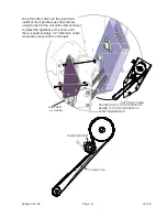
FRONT

FRONT

RIGHT SIDE 
END PLATE

SHAFT
EXTENSION

NUMBER
DECAL

SET SCREW, 
5/16 x 3/8”

NUT, 5/8-11

ASSEMBLED
BEARING
PLATE

POINTER

3/8 HEX NUT

TAP BOLT, 3/8 
x 3 1/2”

5/8 HEX NUT

806

Page  29

Summary of Contents for TURFMAKER Junior SLP2041

Page 1: ...R S MANUAL BRILLION IRON WORKS INC BRILLION WISCONSIN 54110 1P128 706rev7 14 08 MODELS SLP2041 SLP2061 SLPB2041 SLPB2061 Brillion Brillion GRASS SEEDER TURFMAKERJunior BRILLION FARM EQUIPMENT www brillionfarmeq com ...

Page 2: ...1P128 ...

Page 3: ...s 16 Adjustment of Wheel Track Remover 17 Maintenance 18 Lubrication 18 Roller Wheels 18 Chain Tension 19 Acre Meter 19 Feed Cup Adjustment 20 Adjustment Wrenches 21 SECTION II ADDITION OF OPTIONAL REAR SEEDBOX Decal Locations Rear Seedbox 25 Assembly Instructions 26 Rear Box End Plates 26 Deflector 27 Seed Box 28 Right End Seed Shaft Bearing 29 Transmission 30 31 Operating Instructions 32 Seed Ra...

Page 4: ...1P128 ...

Page 5: ...ON BECOME ALERT YOUR SAFETY IS INVOLVED Read the message that follows and be alert to the possibility of personal injury or death Parts Ordering When ordering parts for this machine include the complete model number and serial number Refer to the name plate on the seedbox at the right front Please record these numbers upon taking delivery of the unit Be sure to read the warranty card which is ship...

Page 6: ...e control of tractor Make sure tractor or towing vehicle is heavier than seeder be sure the front of the tractor has enough weight to maintain control when transporting a seeder with a fully loaded seed box 8 When transporting the machine on a road or highway use adequate warning symbols reflectors lights and slow moving vehicle signs as required 9 Lower machine to ground when not in use See page ...

Page 7: ...sult in severe personal injury or death CAUTION A reminder of safety practices or directs attention to unsafe practices which could result in personal injury Examine safety decals and be sure you have the correct safety decals for the machine Keep these signs clean so they can be observed readily It is important to keep these decals cleaned more fre quently than the machine Wash with soap and wate...

Page 8: ...BOUT FRONT AXLE 9J302 CAUTION MOVING MACHINES CAN CAUSE INJURY KEEP AWAY 1 KEEP AWAY FROM MOVING TRACTORS OR IMPLEMENTS KEEP OTHERS AWAY 2 DO NOT RIDE OR ALLOW OTHERS TO RIDE ON TRACTOR OR IMPLEMENT 3 BLOCK IMPLEMENT TO PREVENT MOVEMENT WHEN UNHITCHED FROM TRACTOR 4 KEEP ALL GUARDS AND SHIELDS IN PLACE WHILE MACHINE OR PARTS ARE IN MOTION 8J309 CAUTION Safety Engage Parking Pin P N 9J302 Caution L...

Page 9: ...ING RATES FOR SEED BOX INDICATOR SETTING POUNDS PER ACRE POUNDS PER 1000 SQ FT 1 2 3 4 5 6 7 8 1 2 3 4 5 6 7 8 WARNING MOVING PART HAZARD TO PREVENT SERIOUS INJURY FROM MOVING PARTS KEEP COVERS CLOSED DURING OPERATION DO NOT ALLOW ANYONE TO RIDE OR CLIMB ON MACHINE DURING OPERATION KEEP OBSERVERS AWAY 2K123 Brillion Brillion Turfmaker Junior Brillion Decal P N 4K036 Red Orange P N 8K597 Red P N 2J...

Page 10: ...ip backward on frame 2 Be sure front of tractor has enough weight to maintain control when Transporting a seeder with a fully loaded seed box ATTACHING TO TRACTOR HITCH PIN KLIK PIN FRONT FRONT USE THIS HOLE WHEN DISCONNECTED FROM TRACTOR USE THIS HOLE WHEN CONNECTED TO TRACTOR PARKING PIN KLIK PIN Your Turfmaker Junior Seeder is preassembled at the factory Instructions for the addition of optiona...

Page 11: ... machine and mounting bracket and strap on the right side of machine They are attached at the center holes of the right and left end plates 2 Attach lift sling to mounting brackets with 5 8 x 1 1 2 capscrews and stover nuts provided in kit 3 Slide stablizer into frame tube and secure with clevis pin and hairpin cotter HHCS 5 8 x 1 1 2 HHCS 5 8 x 1 1 2 LOCK NUT 5 8 MOUNT BRACKET LOCK NUT 5 8 MOUNT ...

Page 12: ... the machine Be sure to re close and latch securely when you have finished acre meter installation Remove the bottom rear capscrew from the transmission bracket and use this hardware 5 16 x 1 capscrews lock washers and nuts to attach the 6K447 pick up switch bracket Install it on the rear inside surface of the left side frame end plate Do not tighten screws at this time ACRE METER BRACKET HHCS 3 8...

Page 13: ...mounting bases and wire ties to prevent wire from becoming entangled or rubbing moving parts 9 Program acre counter following the instructions on the next page Note Alignment of pickup switch and magnet wheel is critical Improper alignment will cause the acre counter to record acres erratically or not at all Side View Top View 3 Attach the pick up switch to the top of the 6K447 bracket with two 8 ...

Page 14: ... 18 10 SSP12 SS12 764 18 12 SSP108 SS108 760 17 8 SSP110 SS110 760 17 10 SSP112 SS112 760 17 12 SSP208 SSP2081 SS208 SS2081 764 18 8 SSP210 SSP2101 SS210 SS2101 764 18 10 SSP212 SSP2121 SS212 SS2121 764 18 12 SSP308 SS308 764 18 8 SSP310 SS310 764 18 10 SSP312 SS312 764 18 12 GLP643 SSLP643 917 21 5 SLP10 SL10 4147 95 10 SLP12 SL12 4147 95 12 SLP204 1690 39 4 SLP206 1690 39 6 SLP304 845 19 4 SLP30...

Page 15: ...oll through screens to check that the correct pulses and width have been entered TO ENTER PASSWORD 1 Press function button to scroll to pass screen 2 Pick a number and enter it by using the up or down buttons 3 Press function button to set password number screen will show set Record number it is required if you need to disable password 4 Let screen go blank password is now entered TO DISABLE PASSW...

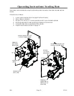
Page 16: ...on the right side end plate See Figure11 IMPORTANT To prevent damage to seed meters do not apply excessive force to adjusting nuts This is especially important when closing meters as seed in flutes can be pinched between cut off and washer in seed cup Do not attempt to open meters more than 1 Feed rolls could become disengaged from washer in seed cup Seed rate is set by adjusting the micro meter o...

Page 17: ...nks included with the seeder Procedure is as follows 1 Loosen drive chain as shown on page 19 Chain Tension 2 Open chain at connector 3 Remove 1 4 roll pin in 13 tooth sprocket and 3 4 nut on 26 tooth sprocket 4 Exchange sprockets to new positions and replace roll pin and nut 5 Add extra chain links as provided with this seeder 6 Adjust chain tension as shown on page 19 Operating Instructions Seed...

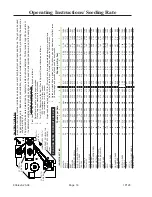
Page 18: ...TUCKY 24 45 85 155 208 259 339 389 0 55 1 03 1 94 3 55 4 77 5 95 7 78 8 93 BUFFALO GRASS 8 40 78 110 134 150 188 0 18 0 91 1 79 2 52 3 07 3 43 4 31 CANOLA 32 94 180 274 384 471 557 619 0 73 2 16 4 13 6 29 8 81 10 81 12 79 14 22 CENTIPEDE 32 78 150 282 447 565 699 777 0 73 1 79 3 43 6 47 10 27 12 97 16 04 17 83 CHICKORY 28 66 122 189 262 335 405 475 0 64 1 52 2 79 4 34 6 01 7 68 9 29 10 90 CLOVER A...

Page 19: ...own Loosen the 4 1 2 capscrews and nuts that secure the clamps to the coil tine supports Adjust the supports up or down to the desired depth and then retighten the nuts on the screws Do this for each pipe and tine assembly CAPSCREW 1 2 13 NC x 1 1 2 Operating Instructions Depth Adjustment 806 Page 17 ...

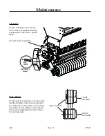
Page 20: ...s should line up with valleys on front wheels This requires adjusting both end clamps on the rear axle drum Maintenance Lubrication Grease all fittings every 20 hours Each of the four flangette bearings supporting the rollers has a grease fitting FRONT ROLLERS AXLE CLAMPS REAR ROLLERS Oil roller chains periodically 20 HRS both R L sides 806 Page 18 ...

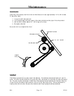
Page 21: ...in Maintenance MOVABLE IDLER FRONT ROLLER STRAIGHT EDGE 1 4 3 4 SLACK IDLER AXLE BOLT Acre Meter The battery operated acre counter uses 3 AA batteries The batteries should last between 5 and 10 years The acre counter will last much longer than that Eventually you will have to replace the batter ies The acre counter will display LObAt when the batteries require replacement Remove the acre counter f...

Page 22: ...eed cups All cups should be completely closed If not individual cups can be adjusted by loosening their mounting bolts moving the cups and then re tightening Pointer Adjustment With cups completely closed pointer should point to groove in hex shaft marked 0 If it does not adjust the nuts which clamp the pointer spring bolt to the frame end plates Be sure pointer reads 0 when cups are complety clos...

Page 23: ... rate Adjustment Store the two seed rate adjusting wrenches provided with the seeder on the end plate on the right side of the seeder Hang them on the rivet that extends through the plate and secure with a hairpin cotter HAIRPIN COTTER RIVET WRENCHES 806 Page 21 ...

Page 24: ...1P128 806 Page 22 ...

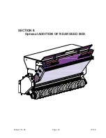
Page 25: ...1P128 SECTION II Optional ADDITION OF REAR SEED BOX 806rev7 14 08 Page 23 ...

Page 26: ...r seedbox when it is added to the Turfmaker Jr machine See pages 4 7 for other important saftey messages and sign locations Be sure machine is unhitched from tractor and blocked securely on the ground before adding rear seedbox Be sure to replace any guards that you remove while working on the machine 806 Page 24 ...

Page 27: ...1 92 LESPEDEZA SERICEA HULLED 12 32 52 75 96 119 143 163 0 28 0 73 1 19 1 03 2 19 2 74 3 29 3 75 LOVE GRASS WEEPING 8 28 47 68 87 107 131 153 0 18 0 64 1 10 1 56 2 01 2 46 3 01 3 57 LOVEGRASS SAND 8 13 40 56 75 96 111 135 0 18 0 55 0 91 1 28 1 74 2 19 2 55 3 11 MILLET 8 28 47 68 87 107 131 153 0 18 0 64 1 10 1 56 2 01 2 46 3 01 3 47 NORTHRUP KING MIXTURE 5 9 13 17 21 25 30 33 0 10 0 21 0 30 0 39 0...

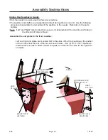
Page 28: ...as if standing behind the machine and facing in the direction of forward travel Assemble the end plates to the front seedbox Left and right end plates are mounted first to the sides of the front seedbox at the position of the 4 holes near the rear of the box as shown below Use 4 5 16 x 3 4 capscrews lockwashers and nuts to attach the left end plate and then do the same for the right side end plate...

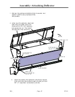
Page 29: ... other deflector was removed with four 3 8 x 1 capscrews lockwashers and nuts 2 At the top of the deflector attach left side to the end plates at the hole shown with a 3 8 x 3 4 capscrew lockwasher and nut Then attach the right side in the same way HHCS 5 16 x 3 4 LOCK WASHER 3 8 HEX NUT 3 8 HHCS 5 16 x 3 4 LOCK WASHER 5 16 HEX NUT 5 16 DEFLECTOR FRAME CHANNEL HHCS 3 8 x 1 LOCK WASHER 3 8 HEX NUT ...

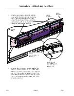
Page 30: ...ng a 1 4 x 1 round head machine screw with a 1 4 lockwasher and nut 3 Bring the rear seedbox and shaft unit into place behind the front seedbox mating the holes in the endplates with those in the sides of the seedbox and again attach to each end plate with 4 5 16 x 3 4 capscrews lockwashers and nuts HHCS 1 4 X 5 8 FLAT WASHER 1 4 LOCK WASHER 1 4 HEX NUT 1 4 RND HD MACHINE SCREW 1 4 X 1 LOCK WASHER...

Page 31: ...nd plate 2 Thread the shaft extension onto the end of the seed shaft loosely snug down the set screw to secure it you may need to adjust the position of the shaft extension later when adjusting feed cups and seeding rate it should be tightened securely at that time and then thread one 5 8 nut onto the shaft end of the seed shaft extension 4 Thread the other 5 8 nut onto the seed shaft extension on...

Page 32: ...replaced so that the guard can be attached at that location PICK UP SWITCH 6K447PICK UP SWITCH BRACKET Use a 1 2 x 1 capscrew lockwasher and nut with nut to the outside here as well to attach the upper angle of the guard to the seedbox end plate at the position shown Attach the guard assembly to the left frame plate Use 2 5 16 capscrews lock washers and nuts Note Install them with the nuts toward ...

Page 33: ...idler sprocket to adjust the tightness of the chain until there is approximately 1 2 deflection under moderate pressure from one finger 6 5 8 SHAFT w 2 HOLES 806rev7 14 08 Page 31 BOTTOM OF CHAIN AROUND THIS 13 TOOTH SPROCKET BEHIND 13 TOOTH SPROCKET OF FRONT TRANSMISION IDLER SPROCKET 1 2 DEFLECTION Adjust Chain Tension ...

Page 34: ... excessive force to adjusting nuts This is especially important when closing meters as seed in flutes can be pinched between cut off and washer in seed cup Do not close meters more than 1 8 when there is seed in the meters without rotating the seed shaft to prevent damage to the rotating washers and retainer rings in the seed meters Do not attempt to open meters more than 1 Feed rolls could become...

Page 35: ...o increase the rate of seeding loosen the outer nut and turn the inner nut to move the seed shaft to the desired lower number position then re tighten the outer nut To adjust and set the seed rate use the adjusting nuts on the micro meter on the right side of the rear seedbox Seed cups discharge to the rear of the machine to aid the tractor driver in determining proper operation 806 Page 33 ...

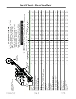
Page 36: ...4 FLAX 8 24 40 52 68 79 92 107 0 18 0 55 0 92 1 19 1 56 1 82 2 09 2 46 HARDING GRASS 8 20 32 43 56 68 79 92 0 18 0 86 0 73 1 00 1 28 1 56 1 82 2 09 HIGHLAND BENT 8 15 23 30 36 43 50 57 0 17 0 35 0 52 0 68 0 84 0 98 1 15 1 31 KLEIN GRASS 8 28 47 68 87 111 135 155 0 18 0 64 1 10 1 56 2 01 2 55 3 11 3 57 LESPEDEZA KOREAN UNHULLED 8 20 36 52 68 84 104 119 0 18 0 36 0 82 1 19 1 56 1 92 2 37 2 74 LESPED...

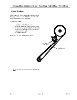
Page 37: ...n the 5 8 idler axle bolt 3 Move the bolt in the slot to obtain enough slack to allow approximately 1 2 deflection when using one finger to apply moderate pressure to the chain 4 Re tighten idler bolt Be careful not to over tighten this chain Note Be sure to oil roller chains periodically 5 8 IDLER AXLE BOLT Operating Instructions Seeding with Rear Seedbox Chain Tension 806 Page 35 ...

Page 38: ... 84 1 2 59 3 4 Overall Length w out Lift Sling 30 30 Overall Height w out Lift Sling 43 43 Three Point Hitch Cat 1 Cat 1 OPTIONAL EQUIPMENT 6K036 Acre Meter 2 6K060 Lift Sling Kit SLP2061 78 6K081 Lift Sling Kit SLP2041 60 6K067 Rear Roller Assembly w 6K066 Sprockets SLP2061 435 6K085 Rear Roller Assembly w 6K066 Sprockets SLP2041 305 6D350 Smooth Wheels front 8 0 ea 6D351 Smooth Wheels rear 4 4 e...

Page 39: ...1P128 ...

Page 40: ...1P128 ...

Page 41: ......

Page 42: ... registration at all Landoll manufacturing facilities LANDOLL CORPORATION 1900 North Street Marysville Kansas 66508 785 562 5381 800 428 5655 WWW LANDOLL COM Copyright 2010 Landoll Corporation All rights reserved including the right to reproduce this material or portions thereof in any form ...

Reviews: