BRILUM S.A.
05-520 Konstancin-Jeziorna, Wilanowska 1A Str.
EMS-60
EN
INSTALLATION AND OPERATING MANUAL
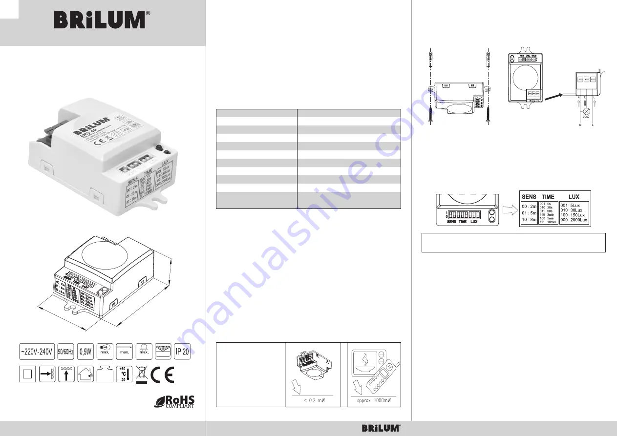
Microwave motion sensor EMS-60
Microwave motion sensor
Microwave sensor emitting high-frequency (5.8GHz) electromagnetic waves, with integrated circuit.
The adwantage of this sensor is easy installation and wide application range. It combines automatism,
convenience, energy-saving and practicality. It works by detecting human’s motion in the motion
detection area and immediately gives the voltage on L’ clamp that receiver (luminaire) is connected
to. The sensor detects the motion trough the door, windows and thin walls. The motion detection
range depends on sensor’s setings. The sensor automatically recognizes the time of the day. It
controls bulbs with total power of 1200W, energy saving lamps with power of 300W and LED light
sources with power of 300W.
TECHNICAL DATA
DETECTION AREA ADJUSTMENT - SENS FUNCTION
Detection area of the motion sensor is adjustable by SENS function. It can be adapted to the place of use:
low detection responsivity for 2m distance, high detection responsivity for 8m distance, apprioprate for
example for large room.
DELAY TIME ADJUSTMENT - TIME FUNCTION
Lighting time counts from the motion detection moment till turning off the light. The delay time
is adjustable and it can be set from minimum value of 5s up to maximum 10min by using TIME
finction. Delay of turning off the light - switching on time duration is modified in continuous way
(„time delay”). It means that during single cycle that is set up by user (once the light is switched on
by sensor) followed by lewving the detection area and next appearing once more in the detection
area, time of lighting is counted from beginning (accordingly to earlier set up of TIME function).
TIME OF THE DAY IDENTYFICATION - LUX FUNCTION
Setting LUX function in position:
“000” – sensor can work regardless the time of the day
“001” – sensor can work in ambient light intensity lower than 5lux
To become acquainted with above adjustment, kindly use the testing pattern.
www.brilum24.pl
www.brilum24.pl
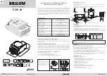
INSTALLATION: (view: scheme)
1. Dissconect power supply.
2. Screw the bottom of the device in chosen position by screws with raw plugs through the holes in
the sensor (Pic.1).
3. Connect the power supply and circuit to the sensor - as on the attached cable connection scheme (Pic. 2).
4. Turn on the power supply and test the sensor.
WARNINGS
➢ Installation should be carried out by experienced electrician.
➢ The device cannot be installed on uneven and unstable surface.
➢ There should not be any obstacles or mobile objects before detector’s shield, the front of the sensor
cannot be covered as it influence the detection.
➢ Avoid installation near metal and glass which can interfere sensor’s operations.
➢ For your own safety the sensor’s cover should not be opened in case of finding a fault.
➢ To avoid damaging the sensor during installation, please install 6A fuse.
➢ The manufacturer is not liable for faults resulting from non-compliance with the above instructions.
According to Article 568 §1 the implied warranty rights regarding physical defects expire after two years
counted from the day that product was delivered to the purchaser.
TROUBLESHOOTING
➢ If the luminaire is not switching on, check:
• power supply and the luminaire,
• is the pilot light on after detection - if yes, check the luminaire,
• is the pilot light on after detection - if not, check if the set up of LUX corresponds to ambient light,
• does the working voltage corresponds to power source.
➢ When the responsivity is low, check:
• if the front of the sensor is not covered by anything,
• if the signal source is in the detection area,
• what the installation height is.
➢ Sensor cannot turn of the luminaire automatically in below cases:
• if there is continuous signal for the sensor in the detection area,
• if the time delay set up is overlong,
• if the receiver’s power is not compliant with the manual.
Pic.1.
Pic.2. Cables connection scheme
TESTING
1.
Setting up SENS switches:
first switch to be set in position „1”, second in position „0”.
Setting up TIME switches:
first and second switch to be set in position „0”, and the third switch in
position „1”.
Setting up LUX switches:
set first, second and third switch in position „0” (Pic.3.).
2. Turn on power supply. The lamp connected to the sensor will turn on autamatically one time and turn
off after set up delay time. If the sensor receives a signal, it will turn on again.
3. If during 5 seconds since first motion detection the sensor does not receive signal, the luminaire should turn off.
Pic.3.
NOTE!
If the device is being tested in the day light, the LUX switch should be set into maximum value 2000
lux, otherwise the sensor may not work.
NOTE!
The high-frequency output of the HF
sensor is < 0.2Mw – it can be
compared to the transmission power
of 5000 mobile phones or output
power of the microwave.
25,5
40,5
58
44g
300W
180°/360°
300VA
Suply voltage and frequency
220V-240VAC 50/60Hz
Waves frequency
5,8GHz CW radar, ISM band
Transmission power
< 0,2mW
Motion detection angle
180° / 360°
Detection area (SENS)
2m, 5m, 8m (to chose from)
Time delay (TIME)
5s, 30s, 90s, 3min, 5min, 10min (to chose from)
Ambient light intensity (LUX)
5 lux, 30 lux, 150 lux, 2000 lux (to chose from)
Installation hight
1,5m ÷ 3,5m
Power consumption
~0,9W
Motion detection speed
0,6 ÷ 1,5m/s
Rated load
1200W (for bulbs),
300W (for energy-saving lamps)
300VA (LED light sources)
1200W


