Document: SLSA-MIP-5-4-0-US
Date of Issue: 05/2016
Revision: -
6-8
Remove the bolt (11) from the stick (4).
Remove the stick (4) from the torque tube (2).
6.3.3
Control sticks installation
Type of maintenance: heavy
Authorization to perform:
LSA mechanic or A&P mechanic (Airframe and Power plant)
Tools needed:
wrench size 7/16 in, 3/8 in
pliers
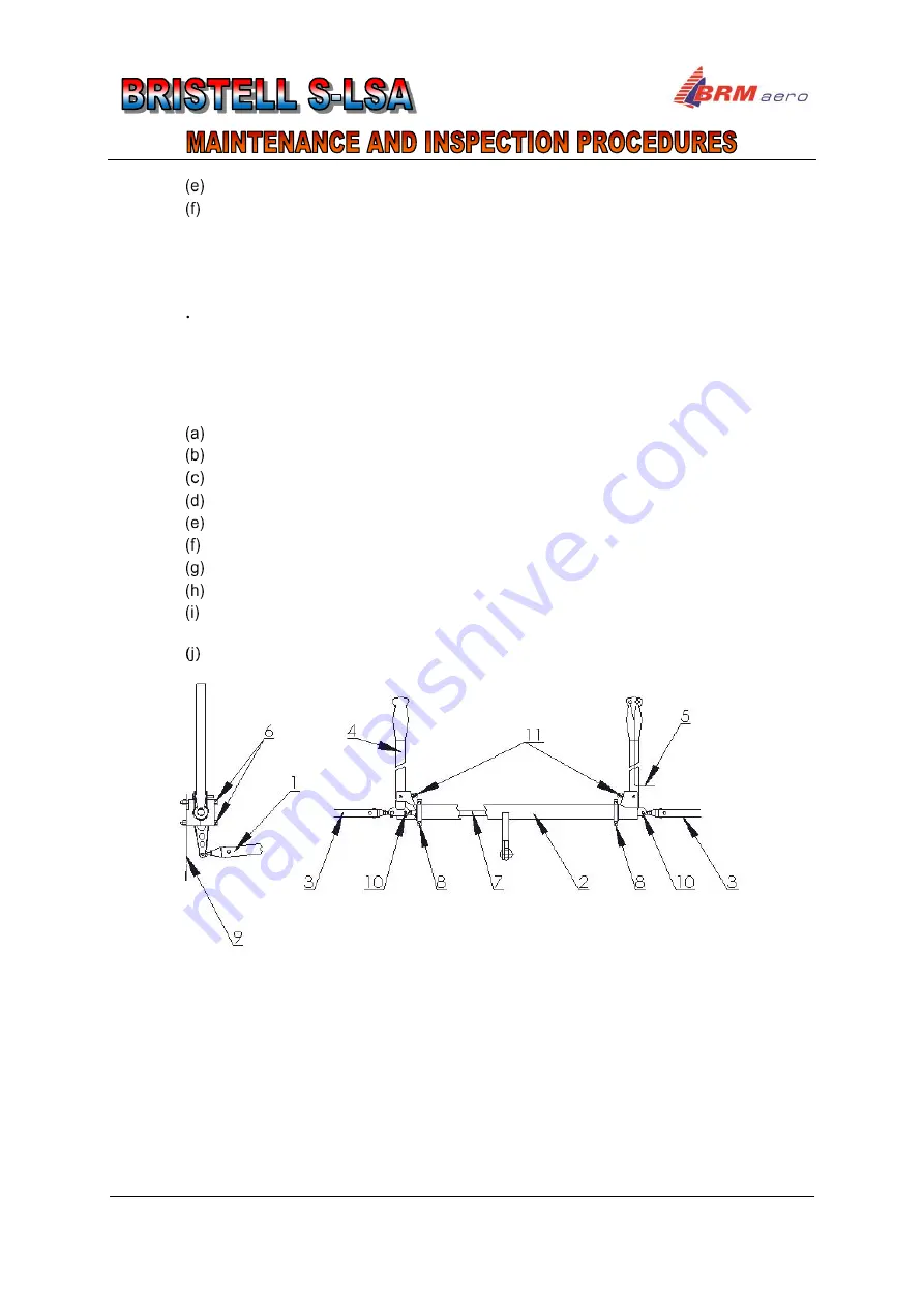
Installation of the control sticks is shown on Fig. 6-7.
Put the stick (4) in the torque tube (2).
Insert the bolt (10) in to the torque tube and stick.
Put the control stick assembly (10) in the hinges (8) on the main wing spar (9).
Insert the bolts (6) and bushings (7) in to the torque tube hinges (8).
Connect electric wire (5) for trim tab switches and PTT.
Put aileron control tube push rods (3) on the sticks (4).
Put elevator control tube push rod (1) in to the torque tube fork (2).
Insert bolt in the control tube fork (2) and screw the nut.
Check aileron deflections (see 6.4.3.1) and check plays in control
(see 6.4.1.3).
Check elevator deflections (see 6.4.3.3) and check plays in control (see 6.4.1.2).
Fig. 6-7
Removal / Installation of the control sticks
View against flight direction
1 - Elevator control rod
2 - Transmission tube
3 - Aileron control rods
4 - Control stick
5 - Electric wire
6 - Connection bolts of transmission
tube hinges on the main center
wing spar
7 - Connection rod
8 - Transmission tube hinges
9 - Main center wing spar
10 - Connection bolts of control
sticks and push rods
11 - Aileron control stop
Summary of Contents for S-LSA
Page 2: ......


