BRITEQ®
20
BTX-700BEAM
1. At last unit, the DMX cable has to be terminated with a terminator. Solder a 120-ohm
1/4W resistor between pin 2(DMX-) and pin 3(DMX+) into a 3-pin XLR-plug and plug it in
the DMX-output of the last unit.
2.
Connect the unit together in a “daisy chain” by XLR plug cable from the output of the unit
to the input of the next unit. The cable cannot be branched or split to a “Y” cable. DMX
512 is a very high-speed signal. Inadequate or damaged cables, soldered joints or
corroded connectors can easily distort the signal and shut down the system.
3. The DMX output and input connectors are pass-through to maintain the DMX circuit,
when one of the units
’ power is disconnected.
4. Each lighting unit needs to have a DMX address to receive the data by the controller. The
address number is between 0-511 (usually 0 & 1 are equal to 1).
5. The end of the DMX 512 system should be terminated to reduce signal errors.
6. 3 pin XLR connectors are more popular than 5 pins XLR.
3 pin XLR: Pin 1: GND, Pin 2: Negative signal (-), Pin 3: Positive signal (+)
5 pin XLR: Pin 1: GND, Pin 2: Negative signal (-), Pin 3: Positive signal (+), Pin4, Pin5 not
used.
7.2 Channel Mode Setting
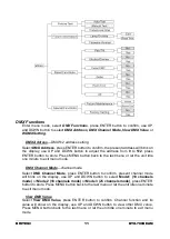
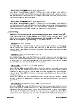
Enter menu mode, select
DMX Functions
, press ENTER button to confirm, use UP and
DOWN button to select
DMX Channel Mode
, press ENTER button to confirm, present
channel mode will blink on the display, use UP and DOWN button to select
Mode1 (18
channels mode)
or
Mode 2 (18 channels mode) or Mode 3 (25 channels mode)
, press
ENTER button to store. Press MENU button back to the last menu or let the unit idle one
minute to exit menu mode.
7.3 Address Setting
If you use a universal DMX controller to control the units, you have to set DMX address
from 1 to 512 so that the units can receive DMX signal.
Press MENU button to enter menu mode, select
DMX Functions
, press ENTER button to
confirm, use UP and DOWN button to select
DMX Address
, press ENTER button to
confirm, the present address will blink on the display, use UP and DOWN button to adjust
the address from 0 to 512, press ENTER button to store. Press MENU button back to the
last menu or let the unit idle one minute to exit menu mode.
Please refer to the following diagram to address your DMX512 channel for the first 4 units.
Channel mode
Unit 1
Address
Unit 2
Address
Unit 3
Address
Unit 4
Address
18 channels
1
19
37
55
25 channels
1
26
51
76
ATTENTION
Termination reduces signal errors and to avoid signal transmission
problems and interference. It is always advisable to connect a DMX terminal
(Resistance 120 ohm 1/4W between pin2 (DMX-) and pin3 (DMX+) of the last
fixture).
Summary of Contents for BTX-700BEAM
Page 1: ......
Page 2: ......
Page 12: ...BRITEQ 10 BTX 700BEAM...
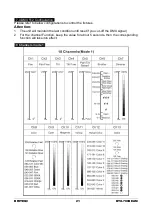
Page 24: ...BRITEQ 22 BTX 700BEAM 18 Channels mode 2...
Page 25: ...BRITEQ 23 BTX 700BEAM...
Page 26: ...BRITEQ 24 BTX 700BEAM 25 Channels mode...
Page 27: ...BRITEQ 25 BTX 700BEAM...
Page 30: ......
Page 31: ......

