Control Board
11
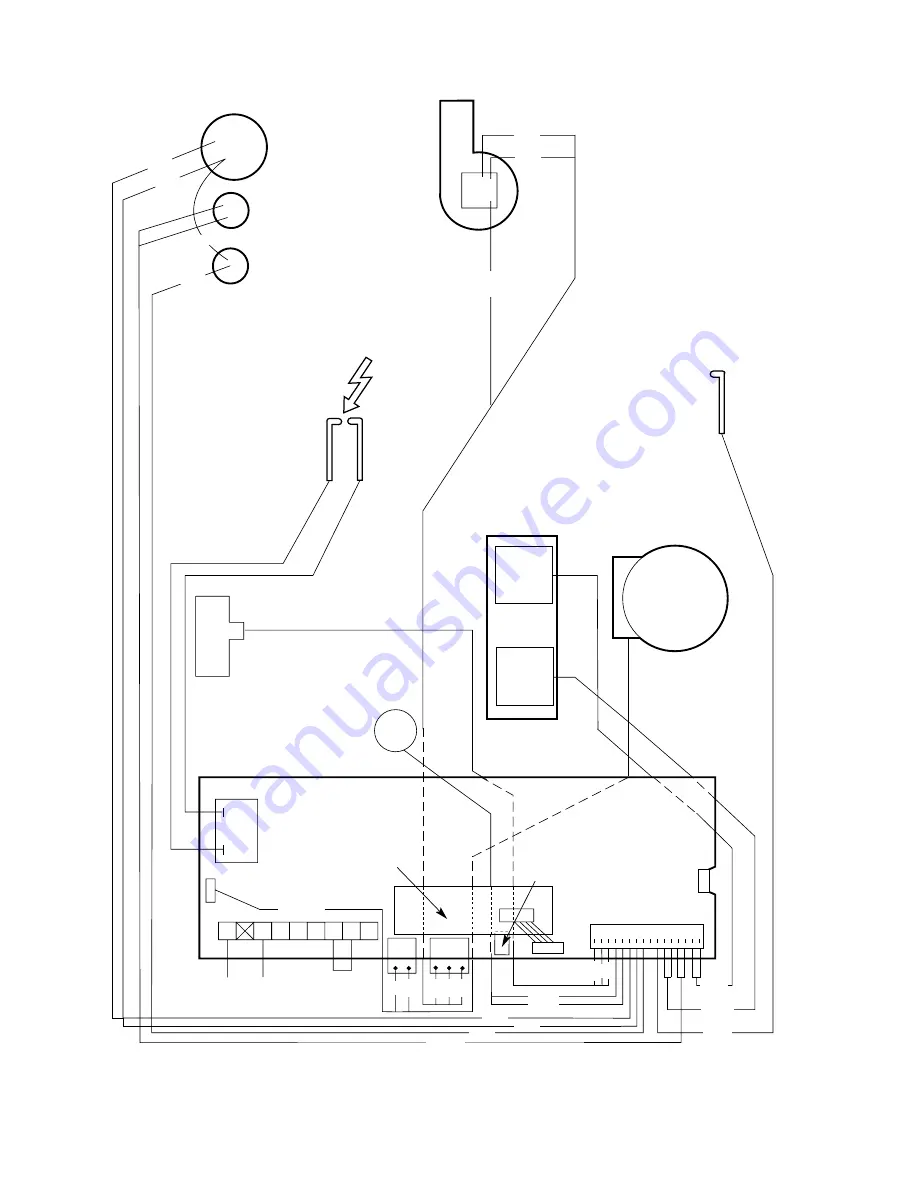
Fig. 12. Wiring diagram.
Fan
Flame sense
electrode
Spark
electrode
Spark
Generator
Mains in
Link
CH sensor
(front of heat
exchanger)
Flow
turbine
ST16
2 blue
green
2 brown
br
own
blue
blue
br
own
green
red
yellow
ST2
ST15
ST1
Pump
Gas valve
black
white
black
Overheat cut-off
device
DHW sensor
Air
Pressure
Switch
2 green
white
black
Code Plug
Regulator
&
Solenoid
Valve
Main
Solenoid
Valve
re
d
black
blue
green/yellow
black
blue
black
red
black
red
white
ST5
Diagnostic
Module
Summary of Contents for RD 628
Page 34: ...34 1 2 3 4 7 5 6 8 9 10 11 12 4 15 13 16 19 14 17 18 20 22 23 21 ...
Page 45: ...45 ...
Page 46: ...46 ...
Page 47: ...47 ...
Page 51: ......
Page 53: ......
Page 55: ...L2 0mm ...
Page 57: ......
Page 58: ...RD 628 USER INSTRUCTIONS CUSTOMER CARE GUIDE G C NUMBER 47 108 14 ...
Page 71: ...14 ...


