Hand over the User Booklet.
Explain how to operate the appliance safely and efficiently.
Tell the user what to do if the appliance is not to be used in very
cold conditions.
Tell the user what to do if the system pressure falls.
Explain that regular servicing will maintain the safe and efficient
operation and extend the life of the appliance.
Tell the user that any work on the appliance must only be
carried-out by a competent, CORGI registered, person.
14.1
To ensure the continued efficient operation of the appliance it must
be checked at regular intervals. The frequency of servicing will
depend upon the particular installation conditions and usage and
can be up to 2 years. The extent of the service required by the
appliance is determined by the operating condition of the
appliance when tested by fully qualified engineers.
Any service work must be carried out by competent registered
engineers such as British Gas or Corgi registered personnel.
14.2 Inspection
Ensure that the appliance is switched off and electrically
isolated before commencing inspection.
Check that the terminal and the terminal guard, if fitted, are clear
and undamaged.
If the appliance is in a compartment or cupboard check that the
specified service space around the appliance is clear. Refer to Table 8.
Check all the joints and connections in the system and remake
any that show signs of leakage. Refill and re-pressurise as
described in Section 12-Commissioning.
Operate the appliance and take note of any irregularities. Refer to
Section 18-Fault Finding for rectification procedures.
Check the combustion performance
Remove the cap from the sample point on the top of the
appliance. Refer to Fig 40.
Connect the sampling meter.
With the appliance at maximum rate and stable in the DHW
mode expect readings of:
CO
2
5.6—6.4% CO 0.006—0.010%
NB For flues greater than 725mm without a restrictor the CO
2
may be up to 0.5% lower.
These figures cover all flue conditions.
Refit the cap after the test.
Disconnect the electrical supply at the mains and turn off the
gas supply at the gas service cock on the appliance before
starting any service procedures.
Always test for gas soundness after the service has been
completed.
14.3 Component Access
To service the appliance it may be necessary to remove some or
all of the following parts to gain access to components which
may need to be checked or replaced.
Cabinet
Pull off the clip-on facia cover. Unscrew the two
screws and release the sides. Lift up and away from
the top locating pegs.
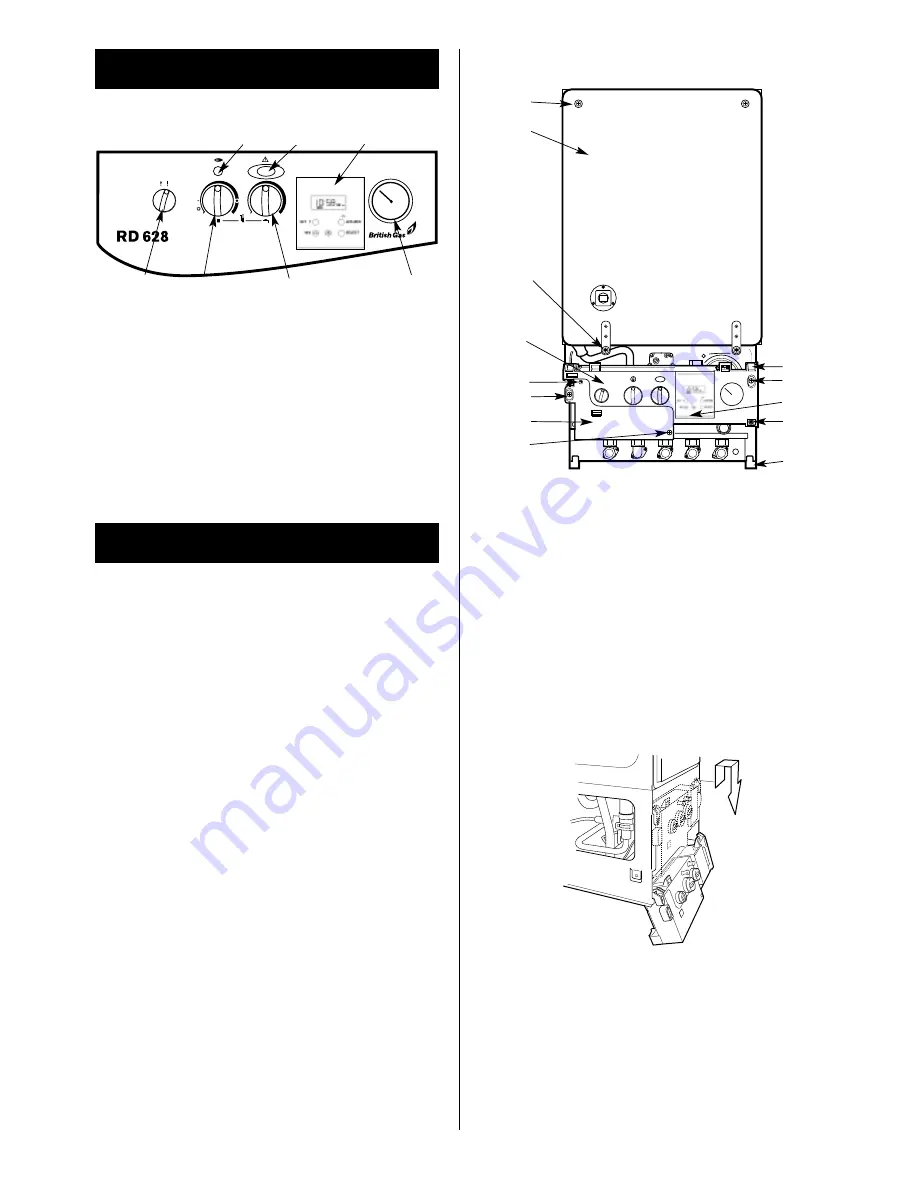
Facia Panel
Unscrew the single screw, lift off and lower onto the
lower support lugs. Refer to Fig 42 & 43.
14. Inspection And Service
13. Handover
24
Fig. 47. Inner case and facia fixing
3
1. Inner casing cover
2. Cabinet fixing screws (4)
3. Inner casing cover fixing screws (2)
4. Inner casing cover fixing screws (2)
5. Facia control panel
6. Controls connector cover
7. Controls connector cover fixing screws (2)
8. Programmer (optional)
9. Facia control panel fixing screw
10. Top support lug (2)
11. Bottom support lug (2)
1
4
5
7
2
6
7
10
9
8
2
11
1
2
3
1. Mains On/Off control
5. Optional programmer
2. CH temperature control
6. Lockout indicator lamp and
3. DHW temperature control
reset button
4. System pressure gauge
7. Burner indicator lamp
4
6
5
7
Fig. 48. Facia in service position
Fig. 46. Facia controls
Summary of Contents for RD 628
Page 34: ...34 1 2 3 4 7 5 6 8 9 10 11 12 4 15 13 16 19 14 17 18 20 22 23 21 ...
Page 45: ...45 ...
Page 46: ...46 ...
Page 47: ...47 ...
Page 51: ......
Page 53: ......
Page 55: ...L2 0mm ...
Page 57: ......
Page 58: ...RD 628 USER INSTRUCTIONS CUSTOMER CARE GUIDE G C NUMBER 47 108 14 ...
Page 71: ...14 ...


