Inner Case Cover
Unscrew the four screws and remove. Refer to Fig 47.
Combustion Chamber
Unscrew the two screws at the top and
the two wing nut extended screws at the sides, pull
forward and remove. Refer to Fig 49.
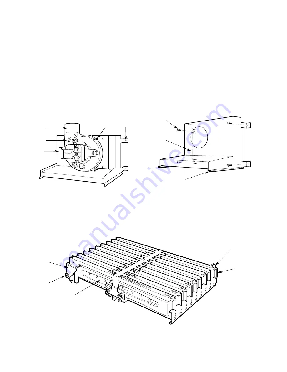
Fan
Carefully pull off the electrical connections and the
tubes from the airflow-sensing device. Unscrew the four
screws and remove the fan assembly. Refer to Fig 50.
Flue Hood
Remove the fan. Unscrew the four screws and slide
out the hood. Refer to Fig 52.
Burner
Remove the combustion chamber. Carefully pull-off
the connections to the spark electrodes. Pull off the
connection to the flame sense electrode. Unscrew
the support bracket. Release the union nut beneath
the burner and carefully remove the burner. Refer to
Fig 51.
14.4 Component Cleaning
Only use a non-metallic brush to clean components.
Do not use a metal probe to clean the injectors.
Clean the fan taking care not to block air flow detector.
Clean the burner to ensure that the blades and injectors are clear.
Clean the electrodes, replace if there is any sign of deterioration.
Clean the heat exchanger.
Cover the gas inlet tube
and remove
any deposits from the heat exchanger from the top and bottom.
Carefully straighten any distorted fins on the heat exchanger.
Check the combustion chamber insulation and replace if there is
any sign of damage or deterioration. Refer to Section 15.5.
Clean the controls in-situ using a non-metallic brush.
Carefully refit any components removed in the reverse order.
Check that all screws are tight and the connections properly
remade with the appropriate gaskets/O-rings.
Re-commission, as necessary, for correct operation to the users
requirements. Refer to Section 12 Commissioning.
26
Fig. 50. Fan assembly
Fig. 52. Flue hood
Fig. 51. Burner assembly
1
2
3
1. Flue hood fixing screws (4)
2. Flue hood
3. Flue hood/Heat exchanger guide
1
2
3
4
1. Fan assembly
2. Fan assembly fixing screws (4)
3. Flue hood
4. Flue hood fixing screws (4)
5. Air Flow detector
2
3
1
4
5
1. Burner assembly
2. Spark electrode assembly
3. Spark electrode assembly fixing screw
4. Flame sense elctrode
5. Flame sense elctrode fixing screw
5
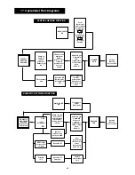
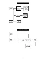
Summary of Contents for RD 628
Page 34: ...34 1 2 3 4 7 5 6 8 9 10 11 12 4 15 13 16 19 14 17 18 20 22 23 21 ...
Page 45: ...45 ...
Page 46: ...46 ...
Page 47: ...47 ...
Page 51: ......
Page 53: ......
Page 55: ...L2 0mm ...
Page 57: ......
Page 58: ...RD 628 USER INSTRUCTIONS CUSTOMER CARE GUIDE G C NUMBER 47 108 14 ...
Page 71: ...14 ...


