background image

7.4. 

INTERCOM  POWER  SUPPLY 

Power  for  the  intercom  circuit  is  provided  from  the +  22  volt 
o utputs  of  the  power  supply  which  are  fed  via  a  noi

s

e  red uct ion 

circuit  and  constant  current  sources. 

7.5. 

TONE  GENERATORS 

The  control  circuit  generates  a  500  Hz  tone  which  is  fed  onto  the 

intercom  circuit  in  certain  circumstances  to  indicate  that  an 

exchange  call  is  waiting  to  be  answered. 

7.6. 

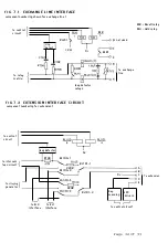
EXCHANGE  LINE  INTERFACE  CIRCUIT 

simplified  exchange  line  interface  circuit  is  shown  in  figure 

7.1. 

Each  exchange  line  interface  circuit  consists  of  the  following 

circuit  elements: 

Loop  detector 

Ringing  detector 
Hold  relay 
Recall  relay 

Surge  protection 
Series  capacitor  and  resistor  to  emulate  DEL  connection 

The  two  detector  outputs  provide  status  informat ion  to  the 

control  chip 

and  the  Hold  and  Recall  relays  are  controlled  by 

the  decoder  chips. 

7.7. 

EXTENSION  INTERFACE  CIRCUITS 

simplified  extension  interface  circuit  is  shown  in  figure  7.2. 

Each  extension  has  an  extension  interface  circuit  which  consists 

of  the  matrix  relays  described  in  7.2., 

together  with 

loop 

detector,  LED  driver  and  scanning  control  circuits 

It  should  be  noted  that  the  relays  for  extension  circuits  1  and  4 

are  ener g ised  for  connection  to  the  intercom  line. 

In  the 

unener gised  or  power  fail  condit ion, 

these  relays  connect 

extension  1  to  exchange  line  1,  and  extension  4  to  exchange  line 

2. 

7.8. 

VOLTAGE  COMPARATOR  CIRCUIT 

This  circuit  element  enables  the  control  circuit  to  determine 

which  button  on  a  key  module  has  been  oper ated. 

Each  button  on 

the  key  module  inserts  a  d ifferent  resistance  into  the  circuit. 

The  resulting  current  flow,  via  the  extension  scanning  circuit  in 

the  extension  interface,  is  applied  to  the  volta ge  comparator 

circuit  which  outputs  a  4-bit  control  word  to  the  control  IC. 

7.9. 

RINGING  GENERATOR 

The  ringing  generator  is  provided  by  an  astable  multivibrator  and 

two  pairs  of  Darlington  transistors. 

terminal  sounder  will  see 

the  output  as  17-25  Hz  and  approximately  75v  peak  to  peak. 

Page  30  of  33 

Summary of Contents for ESCORT

Page 1: ...ESCORT 2 6 ...

Page 2: ......

Page 3: ...BRITISH TELECOM CUSTOMER PREMISES EQUIPMENT E S C 0 R T S Y S T E M MA NUAL Page 1 of 33 ...

Page 4: ...t then please write to CPE MK VS 1 1 2 6 9 Bridgewater Square LONDON EC2Y 8AH Telex 886895 G Issue number 2 Date of Issue 19 01 87 Publication number CP MS 446 c British Telecommunications plc 1986 No part of this publication may be reproduced transmitted transcribed stored in a retrieval system or translated into any human or computer language in any form by any means without the prior permission...

Page 5: ... Mains fail connection and exchangeline ringing 3 8 2 Divert 3 9 Testing 4 Supervisory signals 4 1 Ringing signals 4 2 Lamp signals 4 3 Tones 5 Facilities 5 1 Facilities list 5 2 Facilities description 5 2 1 Intercom 5 2 2 Incoming exchange call 5 2 3 Outgoing exchange call 5 2 4 Exchange line hold 5 2 5 Enquiry 5 2 6 Call transfer 5 2 7 Conference 5 2 7 1 Exchange line conference 5 2 7 2 Internal...

Page 6: ...atrix 7 3 Power supply 7 4 Intercom power supply 7 5 Tone generators 7 6 Exchange line interface circuit 7 7 Extension interface circuit 7 8 Voltage comparator circuit 7 9 Ringing generator 7 10 Incoming exchange line call 8 Specification Page 4 of 33 ...

Page 7: ...ipment is connected to the system via master jacks Fig 1 1 shows the general system configuration The CCU is a wall mounted mains powered unit having a maximum power consumption of 30VA The CCU houses a power supply unit together with two main printed circuit boards each having a 1 3 capacity The system uses custom control and decoder integrated circuits to provide the control and supervisory func...

Page 8: ...for installation and maintenance The CCU should be mounted horizontally ad jacent to a suitable socket outlet such that the markings on the front cover have the correct orient ation There must be at leas t lOO m m clear space all around the CCU to f acilitate servicing and ventilation The CCU should not be mounted above radiators or in direct sunlight Where conditions permit the CCU should be moun...

Page 9: ...OVER RELEASE CATCH RELEASE CATCH ba ___ _ _ r r TTT la I EXCH 2 1EXTN4 I ENTRY FOR EXTN AND EXCH LINE CABLES OPTION SWITCHES BASE TO WALLPLATE SECURING SCREW FIG_3_2 MOUNTING PLATE FIXING DETAILS 123mm 4 96mm I 4Smm I I I 11 _ 1 E E 0 13mm T reference Page 7 of 33 SPARE FUSE SOOmA ANTISURGE ENTRY FOR MAINS CABLE ...

Page 10: ...3 CABLING AND WIRING All the extension and exchange line cables terminate directly on the connection blocks in the CCU as shown in fig 3 1 The cable must be of twisted pair construction with single strand 0 5mm conductors and must be suitable for terminating on Insulation Displacement Connectors IDC It is important that only the correct type of cables are used as the wrong type of cable may result...

Page 11: ...ions 5 2 4 1 6 Circuit Speech A Speech B Ov Key signals LED signals The loop resistance of the extension cables must not exceed that stated for the various approved telephones in the systems PXML The majority of the telephones are approved for a loop resistance of 50 ohms as a gu ide this is equivalent to 300 metres of 0 5 copper cable 3 3 3 Functional Earth Connection The system only requires an ...

Page 12: ...or earth recall provide functional earth and strap B C NOTE 2 For C wire si9nal11n9 provide functional earth and set optlon switch 3 to the ON position NOTE 3 Suitable connectors are B T Block Terminal 58A 12 and Farnell Electronic Comonents order code 146 260 F 16 3 4 CONNECTING THE EXTENSIONS CCU EXTENSION TERMINAL STRIP A BCD E I 000 0 I cable equip 2503 W G G w W 0 B W w B lJU lA 6 1 4 2 5 Con...

Page 13: ... THE MAINS SUPPLY TO THE CCU CCU MAINS CONNECTOR Bro W n wire Blue wire NOTE The CCU does not require a mains protective earth FIG 3 6 CONNECTING A 13AMP PLUG 13 AMP PLUG Blue wire 2 core 5 amp maims f I ex Page 11 of 33 ...

Page 14: ...rmination details for a standard 13 amp plug the plug must be fused at 3 amps 3 4 INSTALLING THE KEY MODULES AND TELEPHONES Fig 3 7 shows the general layout of the key module The key modules may be either free standing or wall mounted using the two key hole slots provided in the base When the key module is wall mounted it should normally be fitted such that its centre is 1350mm from floor level Th...

Page 15: ...sion keys The module extension keys number numerically from left to right omitting their own extension number For example the extension keys on extension 2 are numbered 1 3 4 5 and 6 3 5 SETTING THE OPTION SWITCHES The option switches are set on installation to tailor the system to the customers requirements A 4 way miniature switch block is located adjacent to extension 3 terminal block in the CC...

Page 16: ...valent to 300m of 0 5 copper cable 3 7 EXTENSION BELLS The ringing generator on Escort is designed to ring all extension ports simultaneously provided that the Ringer Equivalent Number REN on each port does not exceed 2 0 Approved extension bells as listed in the systems PXML can therefore be connected to extension ports where the telephone has a REN of one or less The bells are hardwired to termi...

Page 17: ...ck that each ter minal can both make and receive exchange line and intercom calls Remember that if the exc lusive line facility is used only extension 4 will be able to make and receive calls on exchange line 2 If extensions 1 and or 3 are prov ided as two wire extensions check that extension 2 is called when either of these extensions lift their handsets The most common faults likely to be encoun...

Page 18: ...ne of five states SIGNAL Exchange line free Exchange line busy Exchange line ringing Exchange line held Incoming intercom call whilst engaged on an exchange line call 4 3 TONES TONE Call Waiting Tone Introduced on the intercom circuit to indicate that an exchange line call is waiting to be answered INDICATION LED OFF LED ON continuously LED echoes cadence of exchange ringing LED cadenced at 0 5 se...

Page 19: ...om circuit is non secret In the idle state all stations are connected to the intercom circuit and any station lifting its handset will be connected to any existing intercom call in progress or any other station that has lifted its handset and not yet pressed an exchange line key Any station may call any other station by lifting the handset and pressing the required extension key The called station...

Page 20: ...gaged on another call may also answer the call by pressing the key of the calling line If the existing call was an exchange call it will automatically be held 5 2 3 Outgoing exchange call Any station may make an exchange call on any free line by lifting the handset and pressing the line button When exchange dial tone is received the number is dialled from the station telephone At each station the ...

Page 21: ...on key pressed In either case the exchange LED flashes at the hold cadence and if the originating station replaces his handset reminder ringback will be given At the end of the enquiry call the exchange line is reconnected by pressing the key of the held line The exchange LED reverts to steady glow Enquiry to the other exchange line On an established exchange line call any station may make an enqu...

Page 22: ...n and ask him to pick up the call by pressing the line button As soon as the called station presses the line key the call is transferred leaving the enquiring station free to make a follow on call without having to replace his handset Transferring calls to two wire extensions If stations 1 and or 3 are configured for 2 wire working any station initiating a transfer to these stations must use the f...

Page 23: ...another extension or reconnect the exchange line as required Leaving an exchange line conference call An exchange line conference call is cleared by both extensions rep lac ing the ir handse ts If one extension continues in conversation with the exchange line the othe r extension will be reconnected into the conference if he lifts his handset whilst the call is still in progress 5 2 7 2 Internal C...

Page 24: ...are not diverted as two wire stations do not have full access to the systems facilities If the diverting station is the only station programmed to ring on a p articular line diverting calls to a two wire extension could lead to reports of ring tone no reply Station 1 to Station 2 Station 2 to Station 1 Station 3 to Station 1 Station 4 to Station 2 Station 5 to Station 6 Station 6 to Station 5 Note...

Page 25: ...he mode key twice Replace the handset Note that this proceedure cancels the programmed ringing on both exchange lines If the station is still required to ring on one line follow the proceedure descibed for invoking programmed ringing 5 2 10 Exclusive line facility Extension 4 may be set to have exclusive use of exchange line 2 This facility is set on installation by moving switch no 4 of the 4 way...

Page 26: ...ls are diverted to extension 1 with the exception of calls on exchange line 2 which continue to ring at extension 4 To invoke exclusive divert Lift the handset Press and release the mode key Press and release the extension key opposite the mode key Replace the handset The system allows you to alternate between the two divert modes without the need to cancel the existing setting Both modes are canc...

Page 27: ... position sets extensions 1 and 3 for two wire working respectively See sec tion 5 2 6 for the method to be used when transferring calls to two wire extensions To make an intercom call from a two wire extension Lift the handset if the intercom circuit is free extension 2 will be called automatically if the circuit is busy try again later When extension 2 answers ask him to call the required extens...

Page 28: ...inuous ringing signal This is because Escort only senses an extension off ho ok condition during off periods of any incoming ringing cadence Recall If the system is conf i gured for earth recall pressing the mode key on an establ ished call to the PBX will ca use an earth to be appli ed to the line to recall the PBX If the PBX requires timed break recall the recall function must be generated by th...

Page 29: ...e CCU 6 2 TEST CONDITIONS Exchange line Ports The exchange line interface incorporates components to enable it to test as a normal DEL Because the circuit contains voltage dependent resistors for protection it will test low loop if tested with a megger Extension Ports In the idle state i e no calls in progress and all extensions on hook the extensions are connected to the intercom path and a volta...

Page 30: ...CU or extension interface circuit failure A Loss of power supply 1 check fuse 2 check mains supply B failure of control 1 change CCU or power supply circuits 6 3 l Changing the CCU Having proved that the CCU is faulty the unit minus its cover should be replaced as follows First disconnect the unit from the mains supply and then remove the cover Mark for identification purposes and disconnect the w...

Page 31: ...ion on the current status of the extensions and exchange lines and simultaneously scans the module keys looking for and identifying a depressed key From the information gathered the control chip decides what actions are necessary and transmits data to the two decoder chips The decoder chip converts the received data into switching and LED indicator signals which are sent to the extension and excha...

Page 32: ...erface circuit is shown in figure 7 2 Each extension has an extension interface circuit which consists of the matrix relays described in 7 2 together with loop detector LED driver and scanning control circuits It should be noted that the relays for extension circuits 1 and 4 are ener g ised for connection to the intercom line In the unener gised or power fail condit ion these relays connect extens...

Page 33: ...e intercom and ringing highways Flashes the exchange line LED s for that exchange line on all terminals at the incoming ringing cadence During the incoming ringing the Control IC is continually scanning the terminals each complete scan taking 14mS For the exchange line call to be ans wered the Control IC expects to see a terminal off hook signal followed by the depression of the key of the calling...

Page 34: ... c to exchange line RLR Recall relay RLH Hold relay FIG 7 2 EXTENSION INTERFACE CIRCUIT component numbering for extension 1 to control J circuit l to intercom feed circuit to ringing generator I loop detector R100 RL100 1 Ov 6 1 _ 4_7_R RL101 1 220R __ 1 A RL100 2 B T Ov 1 C To extension D E o 3 10 220R 00 4 T RL101 2 Key scanning LED drivers I to EL2 to EL1 interface interface to control circuit ...

Page 35: ...ons of the individual telephones approved for connection 42 volt feed max imum current limited to 80mA The min imum o pen c i rc u it ring ing voltage available at the CCU is 75v peak to peak with frequency between 17 and 25 Hz The ring ing generator is capable of ring ing all six extension po rts simultaneously provided the REN on each port does not exceed 2 0 An exchange line seiz ed condition i...

Page 36: ......

Reviews: