background image

2. 

INSTALLATION 

Installing the CCU.  Do  not connect  the mains  supply to the  CCU  until  all  wiring 

cabling is completed.  First  remove  the  cover  by  prising  out  the  central  BT  logo button  using  a 
Screwdriver  Instrument  No. 

1, 

loosen  the  cover fixing screw  and lift  the  cover  clear, 

(see 

fig. 

1). 

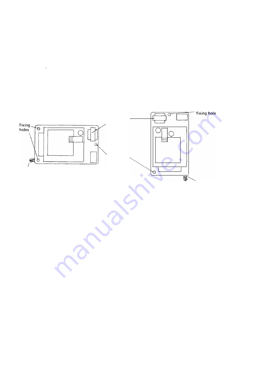
The CCU should  be  screwed to a suitable wall  surface using the three  fixing  holes  in 

the  base.  To  avoid  overheating  make  certain  that  the  mains  transformer is  at  the  top. 

Fig 3 

shows 

the  two  permitted  methods  of mounting the CCU. 

OOO 
DOD 
ODD 

0  0 

DOD 
DODOO 

mains 

transformer 

fixing hole 

D  D 

c:::::J 

D  D 

ODD 

D  D 

ODD 
ODD 

cable entry 

(a)  horizontal mounting 

F/G.3 

(b) vertical mounting 

cable entry 

PERMITTED MOUNTING  OF  CCU 

After  fixing the  CCU and before  cabling the system,  remove the  cover  from the mains  cable 

terminal  blocks 

(see 

fig 

2) 

and  check that  the  cable is correctly  terminated with  the 

green  yellow conductor  to Earth  ( E)  term in al 

Wiring 

the  brown  conductor  to 

Live  ( L)  terminal 

the  blue  conductor  to 

240V 

terminal 

After  checking the terminations  of  the mains  cable  replace  the terminal  block cover. 

All  cables enter  the  CCU  via slots  in  the  lower edge  (when  mounted vertically)  of  the 

back  plate and are fed  through  guides  on  the  right  hand side of the unit.  The  cables  terminate 
under screw  terminals on  the  appropriate terminal  block 

(see 

fig. 

2) 

which are a  push  fit on 

pins  on  the  printed circuit  boards. 

Extensions  are  wired as  ordinary two  wire telephones  with the cables  connected  to 

terminals  A  and  B of  the  terminal  block.  At  the extension,  cables  may  be  either  connected  to 

"Phonesocket"  master  line jacks  or to block  terminals  if  required.  An  extension  may  be 

provided  with  two  high  impedance  telephones  connected  as  a  Phonesocket  installation,  using 
a  secondary  line  jack  for  the  additional  telephone. 

3. 

Summary of Contents for MINIMASTER 1

Page 1: ...CUSTOMERS APPARATUS NOT TO BE SHOWN OUTSIDE BRITISH TELECOM MINIMASTER 1 SMALL ELECTRONIC SWITCHING SYSTEM FOR HOME OR OFFICE 0018 1 6 British TEL ECO TRAININ G 1r 1 EDUCATION DIVISION IDHQ IT5 1 2 ISSUE 1 NOV 1982 ...

Page 2: ......

Page 3: ...ain maximum benefit from them they should be read completely by both Installation and Maintenance staff Contents Page 1 General Description 2 Installation 3 3 Setting Up the System 5 4 Facilities 8 5 Maintenance 11 Graphics and Typesetting by OPPUS V Shirley Solihull PRODUCED BY I DHQ IT5 1 2 2 NOVEMBER 1982 BRITISH TELECOMMUNICATIONS ...

Page 4: ......

Page 5: ... extensions b the expansion board which carries circuitry and terminal blocks for three additional extensions c the power unit which is connected to a 3 metre long mains cable with mains plug fused at 3 amps The telephones which are star connected to the CCU may be any standard telephone using loop disconnect pulsing Difficulty may be experienced in obtaining a satisfactory operation of the tone c...

Page 6: ...Qlc 0 0 0b 0 0 0a 0 Cable Entry Slots Ql b Ql e 0e 0a Q d 0c 0b 0a 0d 0C 0b 0 a 0e 0e 0e 0e COVER FIXING SCREW MAINS CABLE TERMINAL BLOCK COVER FUSE HOLDER 500 ma anti surge fuse Fuse 36A 0 5 Exchange Line Extension 3 Extension 2 Extension 1 Recall earth Mains Cable NOTE Terminal blocks are a push fit on pins or t the printed circuit boards FIG 2 GENERAL ARRANGEMENT OF CCU ...

Page 7: ... terminal blocks see fig 2 and check that the cable is correctly terminated with the green yellow conductor to Earth E terminal Wiring the brown conductor to Live L terminal the blue conductor to 240V terminal After checking the terminations of the mains cable replace the terminal block cover All cables enter the CCU via slots in the lower edge when mounted vertically of the back plate and are fed...

Page 8: ...th six extensions it will be necessary to connect two extensions to the same earth terminal CABLING DISTANCES To ensure satisfactory operation of the system a the maximum loop resistance for an extension with earth loop recall is 60JJ This is equal to a 355 metre run of 0 5 mm copper cable b the maximum loop resistance for extensions where recall is not provided is 100D equivalent to a 595 metre r...

Page 9: ...st Switches FIG 4 ARRANGEMENT OF FACILITY SWITCHES USE FINGERTIP TO GENTLY RELEASE OR OPERATE TH LATCH CLOSED OPERATED FIG 5 SAFETY PIN TYPE SWITCH Exist Switches Exist Switches Switches E 1 to E6 are used to open the extensions for use For an equipped extension the relevant E Switch must be open if an extension is not provided the E switch must be closed This is to ensure that the correct tone is...

Page 10: ...tn 1 Extn 2 Extn 3 Extn 4 Extn 5 Extn 6 4 Extn 1 Extn 3 Extn 5 3 Extn 2 Extn 1 Extn 3 Extn 4 Extn 5 Extn 6 2 Extn 2 1 Extn 1 TABLE 1 Programmable ringing sequence Call Barring Switches A B and C2 to C6 are used with the Call Barring facility There is a choice of four options of barring with two groups of barring within each option Once an option has been selected it will apply to all extensions in...

Page 11: ... v x x v v x x v v x x ISO v x v x v x v x v x OPTIONS Full ISD Access Barred Switch A Open Switch B Closed STD LOCAL v v v v v v v v v v v v v v v v v v v TABLE 2 CALL BARRING OPTIONS ISD x x x x x x x x x x ISD ISD Barred STD Barred Switch A Closed Switch B Open STD LOCAL v v x v v v x v v v x v v x _ _ x y ISO Full Barre Barring Switch A Closed Switch B Closed ISD STD LOCAL x v v x x x x v v x ...

Page 12: ... exchange line calls c Receive incoming exchange line ringing d Answer incoming exchange line calls e Hold exchange line calls f Transfer exchange line calls g Conference calls on exchange line or intercom calls h Divert intercom calls Intercom Calls To make an intercom call lift the handset and listen for system dial tone If the intercom circuit is busy no dial tone will be heard On receipt of sy...

Page 13: ...system ringing is connected to the extension according to the selected ringing programmes Any extension may answer the incoming call if the extension is ringing lift the handset the call is connected auto matically If the extension is not ringing lift the handset and dial digit 8 the call will then be connected to the extension Hold and Transfer An exchange Iine call may be held by either a dialli...

Page 14: ...nder that transfer is still in effect To cancel divert the diverting extension lifts the handset dials digit 0 and then replace the handset Conference A conference call can be set up either between three extensions or two extensions and the exchange line To set up a conference an intercom enquiry call is made and the called extension invited to join the conference To join the conference the invite...

Page 15: ... principal circuit board by means of a plug ended ribbon cable All line terminal blocks are connected to their respective circuit boards as push on connexions to printed circuit board pins The blocks may be prised off the circuit boards to save disconnecting the line and extension terminations when changing circuit boards The power supply must be switched off before the fuse is removed or replaced...

Page 16: ...ly one containing electric motors or other inductive loads Central Control Units that have been maintenance exchanged should be carefully re packed using the packing of the replacement item Full fault details should be included out of ord er is not sufficient and if the item is within warranty period i e within 18 months of the date stamped on the back of the item it should be returned to the manu...

Page 17: ......

Page 18: ......

Reviews: